Toyota Camry (XV70): Identification Information
Vehicle Identification And Serial Numbers
VEHICLE IDENTIFICATION AND SERIAL NUMBERS
VEHICLE IDENTIFICATION NUMBER
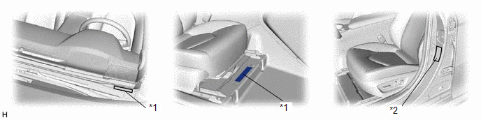
(a) The vehicle identification number is stamped on the vehicle body and on the certification label or name label as shown in the illustration.
|
*1 | Vehicle Identification Number |
*2 | Certification Label or Name Label |
ENGINE SERIAL NUMBER AND TRANSAXLE SERIAL NUMBER
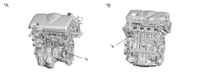
(a) The engine serial number is stamped on the cylinder block of the engine as shown in the illustration.
|
*A | 2GR-FKS |
*B | A25A-FKS |
|
*a | Engine Serial Number |
- | - |
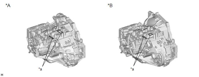
(b) The transaxle serial number is stamped on the transaxle case as shown in the illustration.
|
*A | UA80E |
*B | UB80E, UB80F |
|
*a | Transaxle Serial Number |
- | - |
Vehicle Identification And Serial Numbers
VEHICLE IDENTIFICATION AND SERIAL NUMBERS
VEHICLE IDENTIFICATION NUMBER
(a) The vehicle identification number is stamped on the vehicle body and on the certification label or name label as shown in the illustration.
.png)
|
*1 | Vehicle Identification Number |
*2 | Certification Label or Name Label |
ENGINE SERIAL NUMBER AND TRANSAXLE SERIAL NUMBER
(a) The engine serial number is stamped on the cylinder block of the engine as shown in the illustration.
.png)
|
*A | 2GR-FKS |
*B | A25A-FKS |
|
*a | Engine Serial Number |
- | - |
(b) The transaxle serial number is stamped on the transaxle case as shown in the illustration.
.png)
|
*A | UA80E |
*B | UB80E, UB80F |
|
*a | Transaxle Serial Number |
- | - |
READ NEXT:
 Precaution
PRECAUTION BASIC REPAIR HINT (a) HINTS ON OPERATIONS
1 Attire
Always wear a clean uniform.
A hat and safety shoes must be worn.
2
Vehicle protection Prepare a
Vehicle Lift And Support Locations
VEHICLE LIFT AND SUPPORT LOCATIONS NOTICE ABOUT VEHICLE CONDITION WHEN RAISING VEHICLE
(a) The vehicle must be unloaded before jacking up or raising the vehicle. Never jack up or raise a heavily loa
SEE MORE:
Under Hood
UNDER HOOD GENERAL NOTES
Maintenance requirements vary depending on country.
Check the maintenance schedule in the owner's manual.
Following the maintenance schedule is mandatory.
Determine the appropriate time to service the vehicle using either miles driven or time (months) elapse
Installation
INSTALLATION PROCEDURE 1. INSTALL FUEL INJECTOR SEAL
(a) Apply engine conditioner to the area shown in the illustration. Using a piece of cloth, clean carbon deposits from the fuel injector assembly and its grooves.
NOTICE:
Do not clean the tip of the fuel injector assembly.
Do n
