Toyota Camry (XV70): Vehicle Lift And Support Locations
VEHICLE LIFT AND SUPPORT LOCATIONS
NOTICE ABOUT VEHICLE CONDITION WHEN RAISING VEHICLE
(a) The vehicle must be unloaded before jacking up or raising the vehicle. Never jack up or raise a heavily loaded vehicle.
(b) When removing any heavy components like the engine or transmission, the vehicle center of gravity will shift. To stabilize the vehicle, place a balance weight in a location that will prevent the vehicle from rolling or shifting, or place a transmission jack under the appropriate jack position at the opposite end of the vehicle.
NOTICE FOR USING 4 POST LIFT
(a) Follow the safety procedures outlined in the lift's instruction manual.
(b) Do not damage the tires or wheels while driving onto the lift.
(c) Use wheel chocks to secure the vehicle.
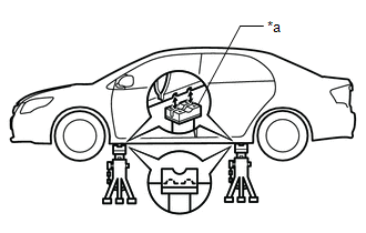
NOTICE FOR USING JACK AND SAFETY STANDS
(a) Work on a level surface. Use wheel chocks at all times.
(b) Use safety stands with rubber attachments as shown in the illustration.
|
*a | Rubber Attachment |
(c) Set the jack and safety stands exactly under the specified locations on the vehicle.
(d) Do not work on or leave the vehicle supported only by a jack. Be sure to support the vehicle with safety stands.
(e) When jacking up the vehicle, first release the parking brake and move the shift lever to N.
(f) When jacking up the entire vehicle:
(1) When jacking up the front wheels first, make sure wheel chocks are behind the rear wheels.
(2) When jacking up the rear wheels first, make sure wheel chocks are in front of the front wheels.
(g) When jacking up only the front or rear wheels of the vehicle:
(1) Before jacking up the front wheels, place wheel chocks on both sides of the rear wheels.
(2) Before jacking up the rear wheels, place wheel chocks on both sides of the front wheels.
(h) When lowering a vehicle that only has its front or rear wheels jacked up.
|
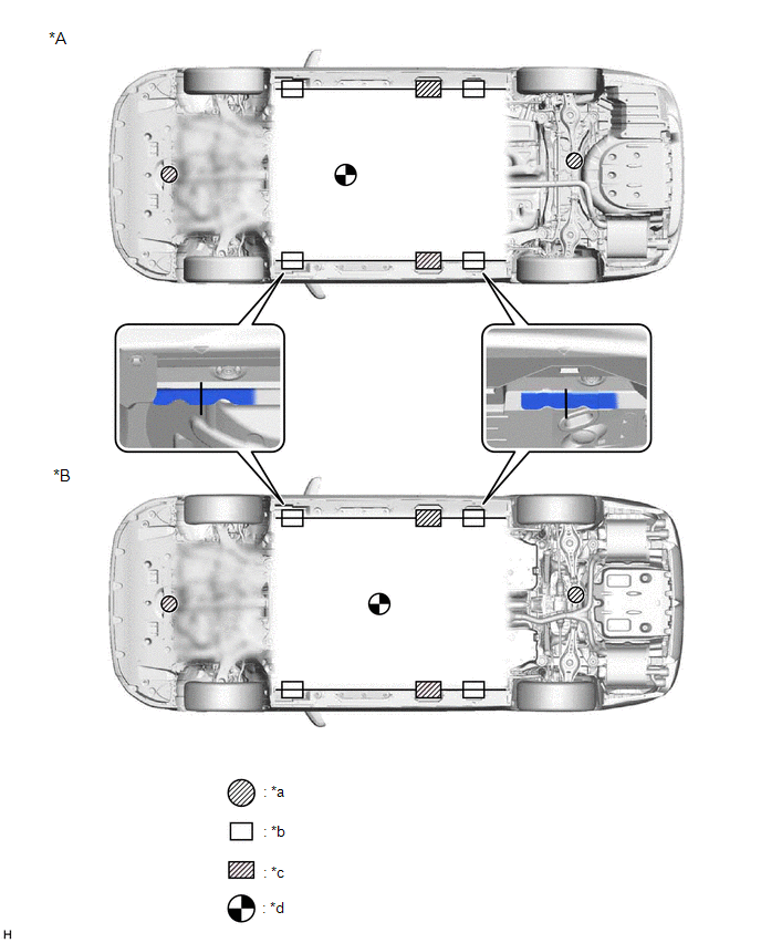
*A | for 2WD |
*B | for AWD |
|
*a | JACK POSITION |
*b | SUPPORT POSITION - Safety stand - Swing arm type lift - Plate type lift |
|
*c | SUPPORT POSITION - Plate type lift (Rear side) |
*d | VEHICLE CENTER OF GRAVITY (Unloaded Condition) |
(1) Before lowering the front wheels, make sure wheel chocks are in front of the rear wheels.
(2) Before lowering the rear wheels, make sure wheel chocks are behind the front wheels.
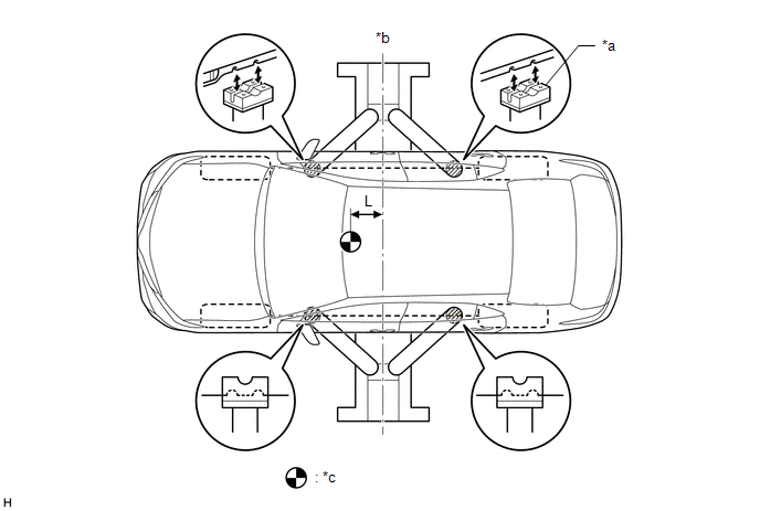
NOTICE FOR USING A SWING ARM TYPE LIFT
(a) Follow the safety procedures outlined in the lift's instruction manual.
(b) Use swing arms equipped with rubber attachments as shown in the illustration.
(c) Position the vehicle so that its center of gravity is centered on the lift (length of "L" in the illustration should be as short as possible).
(d) Ensure that the rubber cushions or swing arms do not contact the body cladding or lower mouldings.
(e) Be sure to lock the swing arms before raising the vehicle (if equipped with arm locks).
(f) Use the lift to raise the vehicle until the tires are off the ground, then stop the lift and shake the front and rear of the vehicle to make sure that it is stable.
|
*a | Rubber Attachment |
*b | Center of lift |
|
*c | VEHICLE CENTER OF GRAVITY (Unloaded Condition) |
- | - |
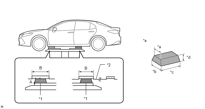
NOTICE FOR USING PLATE TYPE LIFT
(a) Follow the safety procedures outlined in the lift's instruction manual.
(b) Use plate lift attachments (rubber lifting blocks) on top of the plates.
(c) Be sure to set the vehicle to the specified position described in the following chart and shown in the following illustration.
|
Right and left set position |
|
| Front and rear set position |
|
(d) Ensure that the plate lift or rubber lifting blocks do not contact the body cladding or lower mouldings.
(e) Use the lift to raise the vehicle until the tires are off the ground, then stop the lift and shake the front and rear of the vehicle to make sure that it is stable.
|
*1 | Attachment |
*2 | Rocker Panel Moulding |
|
*a | 85 mm (3.35 in.) |
*b | 100 mm (3.94 in.) |
|
*c | 200 mm (7.87 in.) |
*d | 70 mm (2.76 in.) |
|
*e | Attachment Dimensions |
- | - |
READ NEXT:
 Customize Parameters
CUSTOMIZE PARAMETERS PROCEDURE
1. CUSTOMIZE DYNAMIC RADAR CRUISE CONTROL SYSTEM Click here
2. CUSTOMIZE LANE TRACING ASSIST SYSTEM
Click here 3. CUSTOMIZE ROAD SIGN ASSIST SYSTEM
Click her
Initialization
INITIALIZATION
Necessary Procedure Effect/Inoperative Function when Necessary Procedure not Performed
Link Perform steering sensor zero point calibration
Lane Tracing Assist Sys
Precaution
PRECAUTION BASIC REPAIR HINT (a) HINTS ON OPERATIONS
1 Attire
Always wear a clean uniform.
A hat and safety shoes must be worn.
2
Vehicle protection Prepare a
SEE MORE:
Pressure Control Solenoid "L" Circuit Short to Battery (P08BA12)
DESCRIPTION Changing gears is performed by the ECM turning the solenoid (SL1, SL2, SL3, SL4, SL5 and SL6) valves on and off.
If an open or short occurs in any of the solenoid valve circuits, the ECM controls the remaining normal solenoid valves to allow the vehicle to be driven. If all of the sole
Camshaft Position Sensor "A" Bank 1 or Single Sensor Circuit Short to Ground (P034011,P034015,P034511,P034515)
DESCRIPTION The VVT sensor (for intake camshaft) (VV1, VV2 signal) consists of a magnet and MRE (Magneto Resistance Element).
The intake camshaft has a timing rotor for the VVT sensor. When the intake camshaft rotates, changes occur in the air gaps between the timing rotor and MRE, which affects t
