Toyota Camry (XV70): Right Rear Wheel Speed Sensor Internal Electronic Failure (C051249)
DESCRIPTION
When the system is starting up and the skid control ECU (brake actuator assembly) detects a speed sensor circuit malfunction via the speed sensor circuit self-diagnosis function, this DTC is stored.
|
DTC No. | Detection Item |
DTC Detection Condition | Trouble Area |
|---|---|---|---|
|
C051249 | Right Rear Wheel Speed Sensor Internal Electronic Failure |
A circuit malfunction in the speed sensor is detected during the self test. |
|
WIRING DIAGRAM
Refer to DTC C051212.
Click here
.gif)
CAUTION / NOTICE / HINT
NOTICE:
- After replacing the skid control ECU (brake actuator assembly), perform acceleration sensor zero point calibration and system information memorization.
Click here
- After replacing or removing and installing a speed sensor, perform Dealer Mode (Signal Check) inspection to confirm that the speed sensors are operating correctly.
Click here
PROCEDURE
|
1. | CHECK HARNESS AND CONNECTOR (SENSOR CIRCUIT) |
| (a) Make sure that there is no looseness at the locking part and the connecting part of the connectors. OK: The connector is securely connected. |
|
.png)
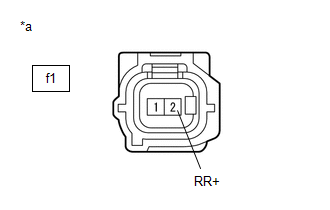
(b) Disconnect the f1 rear speed sensor RH (rear axle hub and bearing assembly RH) connector.
(c) Check both the connector case and the terminals for deformation and corrosion.
OK:
No deformation or corrosion.
(d) Turn the ignition switch to ON.
(e) Measure the voltage according to the value(s) in the table below.
Standard Voltage:
|
Tester Connection | Condition |
Specified Condition |
|---|---|---|
|
f1-2 (RR+) - f1-1 (RR-) |
Ignition switch ON | 11 to 14 V |
| NG | .gif) | GO TO STEP 7 |
|
.gif)
| 2. |
CHECK HARNESS AND CONNECTOR (SENSOR POWER SOURCE CIRCUIT) |
| (a) Make sure that there is no looseness at the locking part and the connecting part of the connectors. OK: The connector is securely connected. |
|
(b) Disconnect the f1 rear speed sensor RH (rear axle hub and bearing assembly RH) connector.
(c) Check both the connector case and the terminals for deformation and corrosion.
OK:
No deformation or corrosion.
(d) Measure the voltage according to the value(s) in the table below.
Standard Voltage:
|
Tester Connection | Condition |
Specified Condition |
|---|---|---|
|
f1-2 (RR+) - Body ground |
Ignition switch off | Below 1.5 V |
| NG | | GO TO STEP 5 |
|
| 3. |
INSPECT SKID CONTROL SENSOR WIRE RH |
| (a) Make sure that there is no looseness at the locking part and the connecting part of the connectors. OK: The connector is securely connected. |
|
.png)
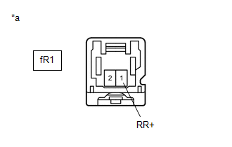
(b) Disconnect the f1 skid control sensor wire RH connector.
(c) Disconnect the fR1 skid control sensor wire RH connector.
(d) Check both the connector case and the terminals for deformation and corrosion.
OK:
No deformation or corrosion.
(e) Measure the resistance according to the value(s) in the table below.
Standard Resistance:
|
Tester Connection | Condition |
Specified Condition |
|---|---|---|
|
f1-1 (RR-) or fR1-2 (RR-) - Body ground and other terminals |
Always | 10 kΩ or higher |
| NG | | REPLACE SKID CONTROL SENSOR WIRE RH |
|
| 4. |
CHECK HARNESS AND CONNECTOR (SKID CONTROL SENSOR WIRE RH - BRAKE ACTUATOR ASSEMBLY) |
(a) Make sure that there is no looseness at the locking part and the connecting part of the connectors.
OK:
The connector is securely connected.
(b) Disconnect the A33 skid control ECU (brake actuator assembly) connector.
(c) Disconnect the fR1 skid control sensor wire RH connector.
(d) Check both the connector case and the terminals for deformation and corrosion.
OK:
No deformation or corrosion.
(e) Measure the resistance according to the value(s) in the table below.
Standard Resistance:
|
Tester Connection | Condition |
Specified Condition |
|---|---|---|
|
fR1-2 (RR-) or A33-29 (RR-) - Body ground |
Always | 10 kΩ or higher |
| OK | | REPLACE REAR AXLE HUB AND BEARING ASSEMBLY RH |
| NG | | REPAIR OR REPLACE HARNESS OR CONNECTOR |
| 5. |
CHECK HARNESS AND CONNECTOR (SENSOR POWER SOURCE CIRCUIT) |
| (a) Make sure that there is no looseness at the locking part and the connecting part of the connectors. OK: The connector is securely connected. |
|
(b) Disconnect the fR1 skid control sensor wire RH connector.
(c) Check both the connector case and the terminals for deformation and corrosion.
OK:
No deformation or corrosion.
(d) Measure the voltage according to the value(s) in the table below.
Standard Voltage:
|
Tester Connection | Condition |
Specified Condition |
|---|---|---|
|
fR1-1 (RR+) - Body ground |
Ignition switch off | Below 1.5 V |
| OK | | REPLACE SKID CONTROL SENSOR WIRE RH |
|
| 6. |
CHECK HARNESS AND CONNECTOR (SKID CONTROL SENSOR WIRE RH - BRAKE ACTUATOR ASSEMBLY) |
| (a) Make sure that there is no looseness at the locking part and the connecting part of the connectors. OK: The connector is securely connected. |
|
(b) Disconnect the A33 skid control ECU (brake actuator assembly) connector.
(c) Disconnect the fR1 skid control sensor wire RH connector.
(d) Check both the connector case and the terminals for deformation and corrosion.
OK:
No deformation or corrosion.
(e) Measure the voltage according to the value(s) in the table below.
Standard Voltage:
|
Tester Connection | Condition |
Specified Condition |
|---|---|---|
|
fR1-1 (RR+) - Body ground |
Always | Below 1.5 V |
| OK | | REPLACE BRAKE ACTUATOR ASSEMBLY |
| NG | | REPAIR OR REPLACE HARNESS OR CONNECTOR |
| 7. |
CHECK HARNESS AND CONNECTOR (SENSOR CIRCUIT) |
| (a) Make sure that there is no looseness at the locking part and the connecting part of the connectors. OK: The connector is securely connected. |
|
.png)
(b) Disconnect the fR1 skid control sensor wire RH connector.
(c) Check both the connector case and the terminals for deformation and corrosion.
OK:
No deformation or corrosion.
(d) Turn the ignition switch to ON.
(e) Measure the voltage according to the value(s) in the table below.
Standard Voltage:
|
Tester Connection | Condition |
Specified Condition |
|---|---|---|
|
fR1-1 (RR+) - fR1-2 (RR-) |
Ignition switch ON | 11 to 14 V |
| OK | | REPLACE SKID CONTROL SENSOR WIRE RH |
|
| 8. |
CHECK HARNESS AND CONNECTOR (SENSOR POWER SOURCE CIRCUIT) |
| (a) Make sure that there is no looseness at the locking part and the connecting part of the connectors. OK: The connector is securely connected. |
|
(b) Disconnect the fR1 skid control sensor wire RH connector.
(c) Check both the connector case and the terminals for deformation and corrosion.
OK:
No deformation or corrosion.
(d) Turn the ignition switch to ON.
(e) Measure the voltage according to the value(s) in the table below.
Standard Voltage:
|
Tester Connection | Condition |
Specified Condition |
|---|---|---|
|
fR1-1 (RR+) - Body ground |
Ignition switch ON | 11 to 14 V |
| NG | | GO TO STEP 11 |
|
| 9. |
CHECK HARNESS AND CONNECTOR (SKID CONTROL SENSOR WIRE RH - BRAKE ACTUATOR ASSEMBLY) |
| (a) Make sure that there is no looseness at the locking part and the connecting part of the connectors. OK: The connector is securely connected. |
|
.png)
(b) Disconnect the A33 skid control ECU (brake actuator assembly) connector.
(c) Disconnect the fR1 skid control sensor wire RH connector.
(d) Check both the connector case and the terminals for deformation and corrosion.
OK:
No deformation or corrosion.
(e) Measure the voltage according to the value(s) in the table below.
Standard Voltage:
|
Tester Connection | Condition |
Specified Condition |
|---|---|---|
|
fR1-2 (RR-) - Body ground |
Always | Below 1.5 V |
| NG | | REPAIR OR REPLACE HARNESS OR CONNECTOR |
|
| 10. |
CHECK HARNESS AND CONNECTOR (SKID CONTROL SENSOR WIRE RH - BRAKE ACTUATOR ASSEMBLY) |
(a) Make sure that there is no looseness at the locking part and the connecting part of the connectors.
OK:
The connector is securely connected.
(b) Disconnect the A33 skid control ECU (brake actuator assembly) connector.
(c) Disconnect the fR1 skid control sensor wire RH connector.
(d) Check both the connector case and the terminals for deformation and corrosion.
OK:
No deformation or corrosion.
(e) Measure the resistance according to the value(s) in the table below.
Standard Resistance:
|
Tester Connection | Condition |
Specified Condition |
|---|---|---|
|
fR1-2 (RR-) - A33-29 (RR-) |
Always | Below 1 Ω |
|
fR1-1 (RR+) or A33-17 (RR+) - fR1-2 (RR-) or A33-29 (RR-) |
Always | 10 kΩ or higher |
| OK | | REPLACE BRAKE ACTUATOR ASSEMBLY |
| NG | | REPAIR OR REPLACE HARNESS OR CONNECTOR |
| 11. |
CHECK HARNESS AND CONNECTOR (SKID CONTROL SENSOR WIRE RH - BRAKE ACTUATOR ASSEMBLY) |
(a) Make sure that there is no looseness at the locking part and the connecting part of the connectors.
OK:
The connector is securely connected.
(b) Disconnect the A33 skid control ECU (brake actuator assembly) connector.
(c) Disconnect the fR1 skid control sensor wire RH connector.
(d) Check both the connector case and the terminals for deformation and corrosion.
OK:
No deformation or corrosion.
(e) Measure the resistance according to the value(s) in the table below.
Standard Resistance:
|
Tester Connection | Condition |
Specified Condition |
|---|---|---|
|
fR1-1 (RR+) - A33-17 (RR+) |
Always | Below 1 Ω |
|
fR1-1 (RR+) or A33-17 (RR+) - Body ground |
Always | 10 kΩ or higher |
| OK | | REPLACE BRAKE ACTUATOR ASSEMBLY |
| NG | | REPAIR OR REPLACE HARNESS OR CONNECTOR |
READ NEXT:
 Multi-axis Acceleration Sensor Module "A" Missing Calibration (C051D54)
DESCRIPTION The airbag sensor assembly has a built-in yaw rate and acceleration sensor and detects the vehicle condition.
The skid control ECU (brake actuator assembly) receives signals from the yaw
Multi-axis Acceleration Sensor Module "A" Circuit Voltage Out of Range (C05201C)
DESCRIPTION The airbag sensor assembly has a built-in yaw rate and acceleration sensor and detects the vehicle condition.
When the skid control ECU (brake actuator assembly) detects an abnormal acce
Multi-axis Acceleration Sensor Module "A" Signal Stuck In Range (C05202A)
DESCRIPTION The airbag sensor assembly has a built-in yaw rate and acceleration sensor and detects the vehicle condition.
The skid control ECU (brake actuator assembly) memorizes the range of the ac
SEE MORE:
Freeze Frame Data
FREEZE FRAME DATA FREEZE FRAME DATA/INFORMATION
(a) Using the Techstream, check the vehicle condition (ECU, sensor) when the brake system operates or a DTC is output.
CHECK FREEZE FRAME DATA AND INFORMATION WHEN DTC WAS STORED (a) Freeze Frame Data is stored when a DTC is output.
(b) Once Free
Components
COMPONENTS ILLUSTRATION
*1 BATTERY
*2 NEGATIVE BATTERY TERMINAL
*3 POSITIVE BATTERY TERMINAL
*4 NO. 2 BATTERY CLAMP
*5 BATTERY TERMINAL CAP
- -
Tightening torque for "Major areas involving basic vehicle performance such as moving
