Toyota Camry (XV70): Road Test
ROAD TEST
PROBLEM SYMPTOM CONFIRMATION
(a) Based on the result of the customer problem analysis, try to reproduce the symptoms. If the problem is that the transaxle does not shift up, shift down, or the shift point is too high or too low, conduct the following road test referring to the automatic shift schedule and simulate the problem symptoms.
ROAD TEST
CAUTION:
- Strictly obey all traffic rules and regulations.
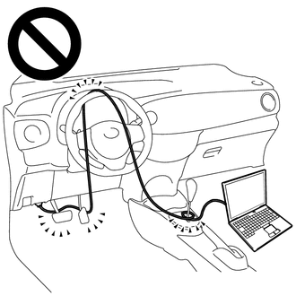
- Do not drive the vehicle with the Techstream cable contacting the pedals, shift lever or steering wheel.
- Driving the wheel with the Techstream cable contacting these areas could impede vehicle control, resulting in a serious accident.
- Do not operate the Techstream while driving the vehicle.
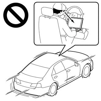
- Operating the Techstream while driving the vehicle will prevent you from paying sufficient attention to vehicle surroundings, and could result in a serious accident.
NOTICE:
- Be sure to inspect and adjust the engine before performing these tests.
- Perform the road test with the engine coolant temperature between 60 and 100
READ NEXT:
 Mechanical System Tests
MECHANICAL SYSTEM TESTS STALL SPEED TEST
CAUTION:
Do not perform a stall test if there are any people or objects near the vehicle.
The vehicle could begin moving suddenly, resulting in a
Hydraulic Test
HYDRAULIC TEST PERFORM HYDRAULIC TEST
CAUTION:
Do not perform a stall test if there are any people or objects near the vehicle.
The vehicle could begin moving suddenly, resulting in a ser
Manual Shifting Test
MANUAL SHIFTING TEST MANUAL SHIFTING TEST
HINT:
Using this test, it can be determined whether a problem is in an electrical circuit or if it is a mechanical problem in the transaxle.
If any
SEE MORE:
Adjustment
ADJUSTMENT PROCEDURE 1. SECURE VEHICLE
(a) Fully apply the parking brake and chock a wheel.
CAUTION:
Make sure to apply the parking brake and chock a wheel before performing this procedure.
If the vehicle is not secure and the shift lever is moved to N, the vehicle may suddenly move, po
Millimeter Wave Radar Sensor Communication Stop Mode
DESCRIPTION
Detection Item Symptom
Trouble Area Millimeter Wave Radar Sensor Communication Stop Mode
Any of the following conditions are met:
Communication stop for "Front Radar" is indicated on the "Communication Bus Check" screen of the Techstream.
Click here
© 2023-2026 Copyright www.tocamry.com
