Toyota Camry (XV70): Short to +B in Outer Mirror Indicator(Slave) (C1AB1)
DESCRIPTION
This DTC is stored when the blind spot monitor sensor LH detects a short to +B in the outer rear view mirror indicator LH.
|
DTC No. | Detection Item |
DTC Detection Condition | Trouble Area |
|---|---|---|---|
|
C1AB1 | Short to +B in Outer Mirror Indicator(Slave) | Both of the following conditions are met:
|
|
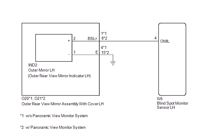
WIRING DIAGRAM
CAUTION / NOTICE / HINT
NOTICE:
When checking for DTCs, make sure that the blind spot monitor system is turned on.
PROCEDURE
| 1. |
CHECK DTC |
(a) Turn the engine switch off.
(b) Turn the engine switch on (IG).
(c) Recheck for DTCs and check if the same DTC is output again.
Body Electrical > Blind Spot Monitor Slave > Trouble CodesOK:
No DTCs are output.
| OK | .gif) |
USE SIMULATION METHOD TO CHECK |
.gif)
|
.gif)
| 2. |
CHECK HARNESS AND CONNECTOR (OUTER REAR VIEW MIRROR INDICATOR CIRCUIT) |
(a) Disconnect the W6 blind spot monitor sensor LH connector.
(b) Measure the voltage according to the value(s) in the table below.
Standard Voltage:
|
Tester Connection | Condition |
Specified Condition |
|---|---|---|
|
W6-4 (OMIL) - Body ground |
Engine Switch on (IG) |
Below 1 V |
| OK | | REPLACE BLIND SPOT MONITOR SENSOR LH
|
|
| 3. |
CHECK HARNESS AND CONNECTOR (OUTER REAR VIEW MIRROR INDICATOR CIRCUIT) |
(a) Disconnect the IND2 outer mirror LH connector.
(b) Measure the voltage according to the value(s) in the table below.
Standard Voltage:
|
Tester Connection | Condition |
Specified Condition |
|---|---|---|
|
W6-4 (OMIL) - Body ground |
Engine Switch on (IG) |
Below 1 V |
| OK | | REPLACE OUTER MIRROR LH |
|
| 4. |
CHECK HARNESS AND CONNECTOR (OUTER REAR VIEW MIRROR INDICATOR CIRCUIT) |
(a) Disconnect the O20*1 or O21*2 outer rear view mirror assembly with cover LH connector.
(b) Measure the voltage according to the value(s) in the table below.
Standard Voltage:
|
Tester Connection | Condition |
Specified Condition |
|---|---|---|
|
W6-4 (OMIL) - Body ground |
Engine Switch on (IG) |
Below 1 V |
- *1: w/o Panoramic View Monitor System
- *2: w/ Panoramic View Monitor System
| OK | | REPLACE OUTER REAR VIEW MIRROR ASSEMBLY WITH COVER LH
|
| NG | | REPAIR OR REPLACE HARNESS OR CONNECTOR |
READ NEXT:
 Short to GND in Outer Mirror Indicator(Master) (C1AB2)
DESCRIPTION This DTC is stored when the blind spot monitor sensor RH detects a short to ground in the outer rear view mirror indicator RH.
DTC No. Detection Item
DTC Detection Condition
Short to GND in Outer Mirror Indicator(Slave) (C1AB3)
DESCRIPTION This DTC is stored when the blind spot monitor sensor LH detects a short to ground in the outer rear view mirror indicator LH.
DTC No. Detection Item
DTC Detection Condition
Open in Outer Mirror Indicator(Master) (C1AB4)
DESCRIPTION This DTC is stored when the blind spot monitor sensor RH detects an open in the outer rear view mirror indicator RH.
DTC No. Detection Item
DTC Detection Condition Trouble A
SEE MORE:
RSA (Road Sign Assist)
Summary of function
The RSA system recognizes specific
road signs using the front
camera and/or navigation system
(when speed limit information is
available) to provide information
to the driver via the display.
If the system judges that the vehicle is being driven over the speed
limit, pe
Right Front Wheel Speed Sensor Supply Voltage Circuit Short to Ground or Open (C14E314)
DESCRIPTION Refer to DTC C050612 Click here
DTC No. Detection Item
DTC Detection Condition Trouble Area
C14E314 Right Front Wheel Speed Sensor Supply Voltage Circuit Short to Ground or Open
An open or short in the speed sensor power supply circuit is detected for 0
