Toyota Camry (XV70): Steering Angle Sensor Supply Voltage Circuit Circuit Short to Ground or Open (C14FE14)
DESCRIPTION
This DTC is stored when the skid control ECU (brake actuator assembly) receives a +B line open signal from the steering angle sensor.
|
DTC No. | Detection Item |
DTC Detection Condition | Trouble Area |
|---|---|---|---|
|
C14FE14 | Steering Angle Sensor Supply Voltage Circuit Circuit Short to Ground or Open |
With the +BS terminal voltage between 9.6 and 16.5 V, a steering angle sensor power supply circuit malfunction signal is received from the steering angle sensor. |
|
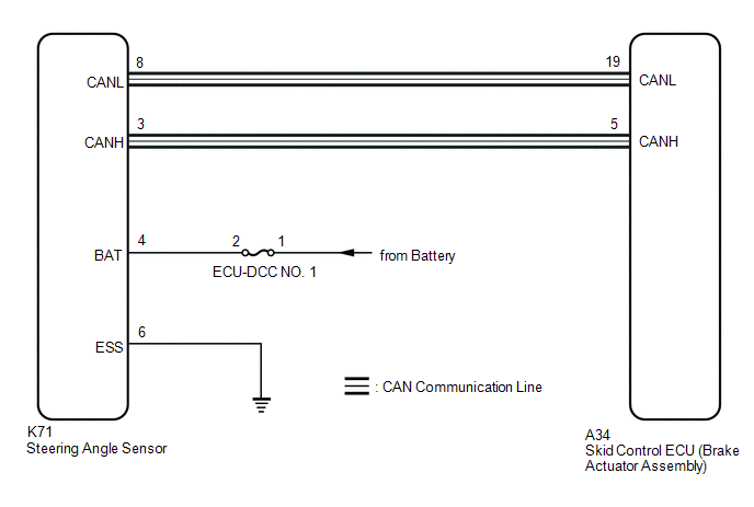
WIRING DIAGRAM
CAUTION / NOTICE / HINT
NOTICE:
Inspect the fuses for circuits related to this system before performing the following procedure.
PROCEDURE
| 1. |
CLEAR DTC |
(a) Connect the Techstream to the DLC3.
(b) Turn the ignition switch to ON.
(c) Operate the Techstream to clear the codes. Enter the following menus: Chassis / Brake/EPB / Trouble Codes.
Chassis > Brake > Clear DTCs(d) Press the DTC clear button.
|
.gif)
| 2. |
RECONFIRM DTC |
(a) Connect the Techstream to the DLC3.
(b) Start the engine.
(c) Perform a road test under the same malfunction conditions recreated based on the Freeze Frame Data or customer problem analysis.
(d) Read the DTCs following the prompts on the Techstream. Enter the following menus: Chassis / Brake/EPB / Trouble Codes.
Chassis > Brake > Trouble Codes(e) Check if the same DTC is output.
|
Result | Proceed to |
|---|---|
|
C14FE14 is not output |
A |
| C14FE14 is output |
B |
| A |
.gif) | USE SIMULATION METHOD TO CHECK
|
.gif)
|
| 3. |
CHECK HARNESS AND CONNECTOR (POWER SOURCE TERMINAL) |
| (a) Remove the steering wheel and column cover. |
|
(b) Make sure that there is no looseness at the locking part and the connecting part of the connector.
OK:
The connector is securely connected.
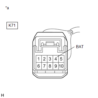
(c) Disconnect the K71 steering angle sensor connector.
(d) Check both the connector case and the terminals for deformation and corrosion.
OK:
No deformation or corrosion.
(e) Measure the voltage according to the value(s) in the table below.
Standard Voltage:
|
Tester Connection | Condition |
Specified Condition |
|---|---|---|
|
K71-4 (BAT) - Body ground |
Always | 11 to 14 V |
| OK | | REPLACE STEERING ANGLE SENSOR |
| NG | | REPAIR OR REPLACE HARNESS OR CONNECTOR |
READ NEXT:
 Brake Switch "A" Circuit Short to Ground (P057111)
DESCRIPTION The skid control ECU (brake actuator assembly) receives stop light switch assembly signals and uses them to determine whether or not the brakes are applied.
When the brake pedal is depre
Brake Switch "A" Circuit Short to Battery (P057112)
DESCRIPTION The skid control ECU (brake actuator assembly) receives stop light switch assembly signals and uses them to determine whether or not the brakes are applied.
DTCs may be stored if either
Brake Switch "A" Circuit Open (P057113)
DESCRIPTION The skid control ECU (brake actuator assembly) receives stop light switch assembly signals and uses them to determine whether or not the brakes are applied.
The skid control ECU (brake a
SEE MORE:
Cleaning and protecting
the vehicle interior
The following procedures will help protect your vehicle's interior
and keep it in top condition:
Protecting the vehicle interior
Remove dirt and dust using a vacuum cleaner. Wipe dirty surfaces
with a cloth dampened with lukewarm water.
If dirt cannot be removed, wipe it off with a soft cl
Replacement
REPLACEMENT CAUTION / NOTICE / HINT
The necessary procedures (adjustment, calibration, initialization or registration) that must be performed after parts are removed and installed, or replaced during automatic transaxle fluid replacement are shown below. Necessary Procedures After Parts Removed/In
