Toyota Camry (XV70): System Diagram
SYSTEM DIAGRAM
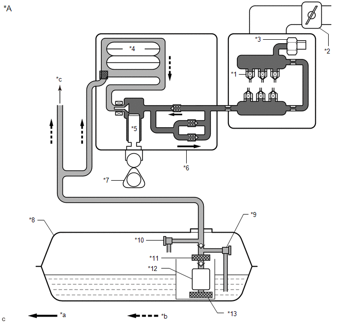
FUEL FLOW DIAGRAM
|
*A | for Direct Injection |
- | - |
|
*1 | Fuel Injector Assembly |
*2 | Throttle Body with Motor Assembly |
|
*3 | Fuel Pressure Sensor (Fuel Delivery Pipe with Sensor Assembly LH) (for High Pressure) |
*4 | Fuel Pressure Pulsation Damper Assembly |
|
*5 | Plunger |
*6 | Fuel Pump Assembly (for High Pressure) |
|
*7 | Camshaft |
*8 | Fuel Tank Assembly |
|
*9 | Fuel Main Valve Assembly (for Low Pressure) |
*10 | Fuel Main Valve Assembly (for High Pressure) |
|
*11 | Fuel Filter |
*12 | Fuel Pump (for Low Pressure) |
|
*13 | Suction Filter |
- | - |
|
*a | High Pressure Fuel Line |
*b | Low Pressure Fuel Line |
|
*c | to Fuel Injector Assembly (for Port Injection) |
- | - |
|
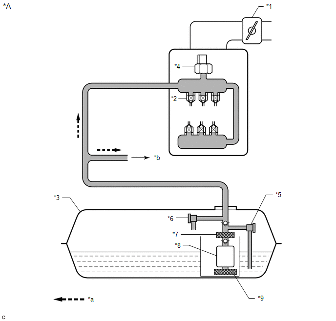
*A | for Port Injection |
- | - |
|
*1 | Throttle Body with Motor Assembly |
*2 | Fuel Injector Assembly |
|
*3 | Fuel Tank Assembly |
*4 | Fuel Pressure Sensor (Fuel Delivery Pipe with Sensor Assembly) (for Low Pressure) |
|
*5 | Fuel Main Valve Assembly (for Low Pressure) |
*6 | Fuel Main Valve Assembly (for High Pressure) |
|
*7 | Fuel Filter |
*8 | Fuel Pump (for Low Pressure) |
|
*9 | Suction Filter |
- | - |
|
*a | Low Pressure Fuel Line |
*b | to Fuel Pump Assembly (for High Pressure) |
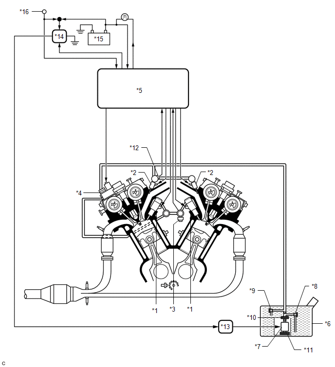
ELECTRICAL CONTROL DIAGRAM
|
*1 | Fuel Injector Assembly (for Direct Injection) |
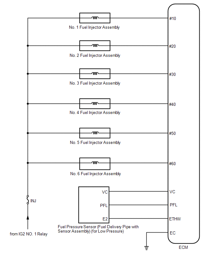
*2 | Fuel Injector Assembly (for Port Injection) |
|
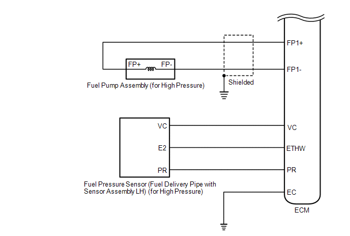
*3 | Fuel Pressure Sensor (Fuel Delivery Pipe with Sensor Assembly LH) (for High Pressure) |
*4 | Fuel Pump Assembly (for High Pressure) |
|
*5 | ECM |
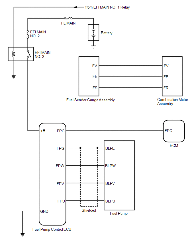
*6 | Fuel Tank Assembly |
|
*7 | Fuel Pump (for Low Pressure) |
*8 | Fuel Main Valve Assembly (for Low Pressure) |
|
*9 | Fuel Main Valve Assembly (for High Pressure) |
*10 | Fuel Filter |
|
*11 | Suction Filter |
*12 | Fuel Pressure Sensor (Fuel Delivery Pipe with Sensor Assembly) (for Low Pressure) |
|
*13 | Fuel Pump Control ECU |
*14 | EFI MAIN NO. 2 Relay |
|
*15 | Battery |
*16 | Engine Switch |
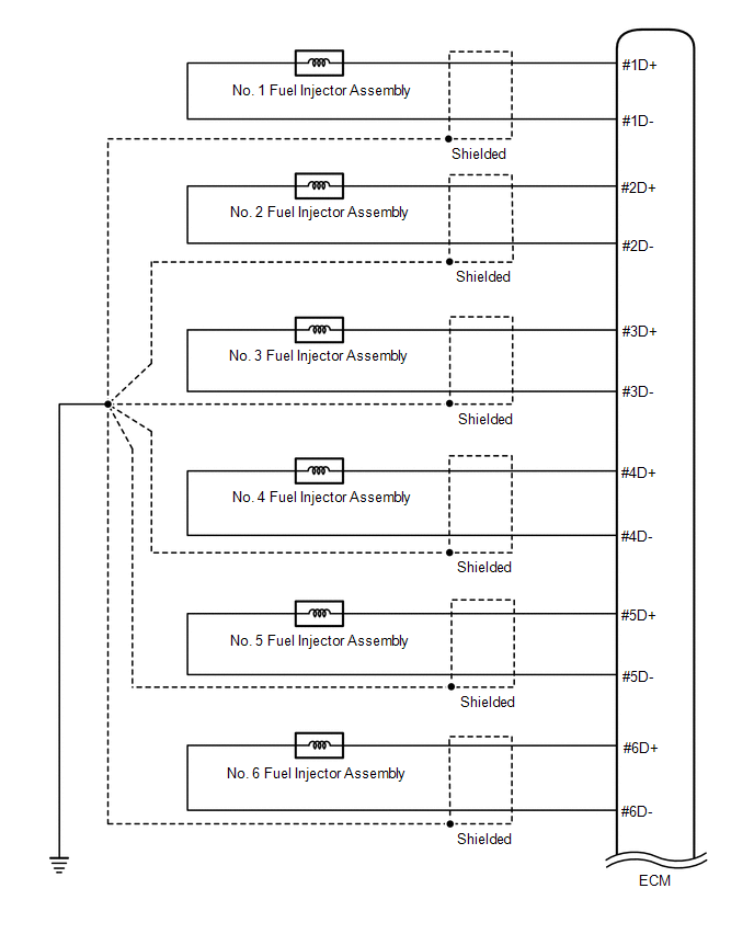
HIGH PRESSURE SIDE FUEL SYSTEM WIRING DIAGRAM
LOW PRESSURE SIDE FUEL SYSTEM WIRING DIAGRAM
READ NEXT:
 On-vehicle Inspection
ON-VEHICLE INSPECTION PROCEDURE
1. CHECK FUEL PUMP OPERATION AND INSPECT FOR FUEL LEAK (a) Check fuel pump operation.
(1) Connect the Techstream to the DLC3. (2) Turn the engine switch on (IG).
SEE MORE:
Dcm Operation History
DCM OPERATION HISTORY DCM OPERATION HISTORY
HINT:
This function shows the telematics network status when the DCM (telematics transceiver) was operated. Use this when no DTC is present but this telematics system was unable to connect to the call center. This symptom may occur if cell phone sign
Back-up Light Bulb
ComponentsCOMPONENTS ILLUSTRATION
*1 BACK-UP LIGHT BULB
*2 LUGGAGE COMPARTMENT DOOR COVER RemovalREMOVAL CAUTION / NOTICE / HINT
HINT:
Use the same procedure for the RH side and LH side.
The following procedure is for the LH side.
PROCEDURE 1. REMOVE LUGGAGE COMP
