Toyota Camry (XV70): Terminals Of Ecu
TERMINALS OF ECU
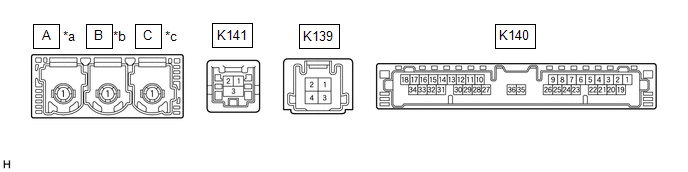
DCM (TELEMATICS TRANSCEIVER)
|
*a | to Telephone Antenna (Sub) |
*b | to GPS Antenna |
|
*c | to Telephone Antenna (Main) |
- | - |
|
Terminal No. (Symbol) | Wiring Color |
Terminal Description | Condition |
Specified Condition |
|---|---|---|---|---|
|
K141-1 (USB-) | - |
USB communication line |
- | - |
|
K141-2 (USB+) | - |
USB communication line |
- | - |
|
K141-3 (USBS) - Body ground |
Shielded - Body ground |
Shield ground | Always |
Below 1 V |
|
K140-31 (USBG) - Body ground |
GR - Body ground | DCM (Telematics Transceiver) power supply ground signal |
Always | Below 1 V |
|
K140-17 (VOT+) - K140-20 (E) |
R - W-B | Sent voice signal |
Calling while using the operator service |
A waveform synchronized with the voice signals received voice is output |
|
K140-15 (USBV) - K140-20 (E) |
L - W-B | DCM (Telematics Transceiver) power supply signal |
Ignition switch off | Below 1 V |
|
Ignition switch to ON |
4.5 to 5.25 V | |||
|
K140-33 (VOT-) - K140-20 (E) |
G - W-B | Sent voice signal |
Calling while using the operator service |
A waveform synchronized with the received voice is output |
|
K140-34 (VOR-) - K140-20 (E) |
W - W-B | Receive voice signal |
Receiving a call while using the operator service |
A waveform synchronized with the sent voice is output |
|
K140-18 (VOR+) - K140-20 (E) |
B - W-B | Receive voice signal |
Receiving a call while using the operator service |
A waveform synchronized with the sent voice is output |
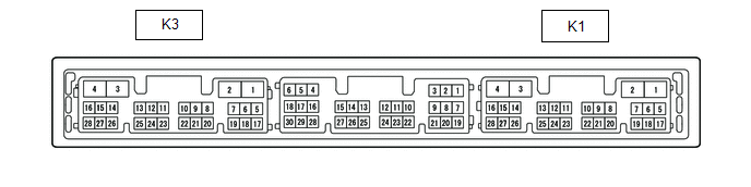
RADIO AND DISPLAY RECEIVER ASSEMBLY
|
Terminal No. (Symbol) | Wiring Color |
Terminal Description | Condition |
Specified Condition |
|---|---|---|---|---|
|
K1-15 (VOT+) - K3-1 (GND1) |
B - BR | Sent voice signal |
Destination assist service in use and vehicle occupant speaking to operator |
A waveform synchronized with the sent voice is output |
|
K1-10 (USBV) - K3-1 (GND1) |
L - BR | DCM (Telematics transceiver) power supply |
Ignition switch to ON |
4.75 to 5.25 V |
|
Ignition switch off | A waveform synchronized with sound is output | |||
|
K1-11 (USBG) - K3-1 (GND1) |
GR - BR | DCM (Telematics Transceiver) power supply ground signal |
Always | Below 1 V |
|
K1-13 (VOR+) - K3-1 (GND1) |
R - BR | Receive voice signal |
Destination assist service in use and operator speaking to vehicle occupant |
A waveform synchronized with the received voice is output |
|
K1-14 (VOR-) - K3-1 (GND1) |
G - BR | Receive voice signal |
Destination assist service in use and operator speaking to vehicle occupant |
A waveform synchronized with the received voice is output |
|
K1-15 (VOT+) - K3-1 (GND1) |
B - BR | Sent voice signal |
Destination assist service in use and operator speaking to vehicle occupant |
A waveform synchronized with the voice signals received voice is output |
|
K1-16 (VOT-) - K3-1 (GND1) |
W - BR | Sent voice signal |
Destination assist service in use and vehicle occupant speaking to operator |
A waveform synchronized with the sent voice is output |
NAVIGATION ECU (w/ Navigation System)

|
Terminal No. (Symbol) | Wiring Color |
Terminal Description | Condition |
Specified Condition |
|---|---|---|---|---|
|
K137-2 (USB4-) | - |
USB communication line |
- | - |
|
K137-1 (USB4+) | - |
USB communication line |
- | - |
|
K137-3 (UGD4) - Body ground |
Shielded - Body ground |
Shield ground | Always |
Below 1 V |
READ NEXT:
 GPS Mark is not Displayed
CAUTION / NOTICE / HINT
NOTICE:
Depending on the parts that are replaced during vehicle inspection or maintenance, performing initialization, registration or calibration may be needed. Refer to
Confirm Cellular Phone Functionality
PROCEDURE
1. CHECK CUSTOMER'S CELLULAR PHONE COMPATIBILITY
(a) Check if the cellular phone is compatible (Refer to http://www.toyota.com/Entune/).
Result Proceed to
Cel
Confirm Vehicle Headunit Functionality
PROCEDURE
1. CHECK CUSTOMER'S CELLULAR PHONE COMPATIBILITY
(a) Check if the cellular phone is compatible (Refer to http://www.toyota.com/Entune/).
Result Proceed to
Cel
SEE MORE:
Removal
REMOVAL CAUTION / NOTICE / HINT
The necessary procedures (adjustment, calibration, initialization or registration) that must be performed after parts are removed and installed, or replaced during fuel pump control ECU removal/installation are shown below. Necessary Procedures After Parts Removed/I
Installation
INSTALLATION PROCEDURE 1. INSTALL STEREO COMPONENT AMPLIFIER ASSEMBLY
2. INSTALL NO. 2 AMPLIFIER BRACKET (a) Install the No. 2 amplifier bracket with the 2 screws.
3. INSTALL NO. 1 AMPLIFIER BRACKET (a) Install the No. 1 amplifier bracket with the 2 screws.
4. INSTALL STEREO COMPONENT AMPLIFIE
