Toyota Camry (XV70): 4wd Control Ecu
Components
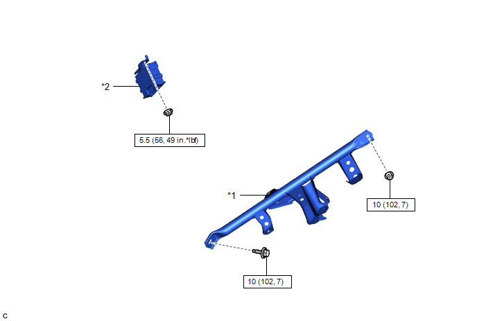
COMPONENTS
ILLUSTRATION
|
*1 | NO. 3 INSTRUMENT PANEL TO COWL BRACE SUB-ASSEMBLY |
*2 | 4WD ECU ASSEMBLY |
.png) |
N*m (kgf*cm, ft.*lbf): Specified torque |
- | - |
Removal
REMOVAL
CAUTION / NOTICE / HINT
The necessary procedures (adjustment, calibration, initialization or registration) that must be performed after parts are removed and installed, or replaced during 4WD ECU assembly removal/installation are shown below.
Necessary Procedures After Parts Removed/Installed/Replaced|
Replaced Part or Performed Procedure |
Necessary Procedure | Effect/Inoperative Function when Necessary Procedure not Performed |
Link |
|---|---|---|---|
|
Battery terminal is disconnected/reconnected |
Perform steering sensor zero point calibration |
Lane Tracing Assist System |
|
|
Pre-collision system | |||
|
Memorize steering angle neutral point |
Parking assist monitor system |
| |
|
Panoramic view monitor system |
|
PROCEDURE
1. REMOVE LOWER NO. 1 INSTRUMENT PANEL AIRBAG ASSEMBLY
Click here
.gif)
2. REMOVE NO. 3 INSTRUMENT PANEL TO COWL BRACE SUB-ASSEMBLY
Click here
3. REMOVE 4WD ECU ASSEMBLY
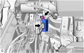
(a) Disconnect the 4WD ECU assembly connector.
(b) Remove the nut and 4WD ECU assembly from the instrument panel reinforcement assembly.
Installation
INSTALLATION
PROCEDURE
1. INSTALL 4WD ECU ASSEMBLY
(a) Install the 4WD ECU assembly to the instrument panel reinforcement assembly with the nut.
Torque:
5.5 N
READ NEXT:
 Precaution
PRECAUTION IGNITION SWITCH EXPRESSION HINT:
The type of ignition switch used on this model differs depending on the specifications of the vehicle. The expressions listed in the table below are used
Parts Location
PARTS LOCATION ILLUSTRATION
*1 BRAKE ACTUATOR ASSEMBLY
- SKID CONTROL ECU *2
ECM *3
FRONT SPEED SENSOR LH
*4 FRONT SPEED SENSOR RH
*5 REAR SKID CONTR
SEE MORE:
Noise Occurs
PROCEDURE
1. CHECK NOISE CONDITION
(a) Check from which direction the noise comes (front left or right, or rear left or right).
OK: The location of the noise source can be determined.
NG
GO TO STEP 3
OK
2.
CHECK SPEAKERS (a
Slave Module Horizontal Axis Misalignment (C1AC2)
DESCRIPTION This DTC is stored when the angle of the blind spot monitor sensor LH deviates more than the allowable range from the horizontal axis.
HINT:
If a drum tester such as a speedometer tester, brake/speedometer combination tester or chassis dynamometer is used with the blind spot monito
