Toyota Camry (XV70): ABS Malfunction (C1296)
DESCRIPTION
If a malfunction in the speed sensor signal circuit or yaw rate and acceleration sensor (airbag sensor assembly) circuit occurs, the 4WD ECU assembly will output this DTC.
The airbag sensor assembly has a built-in yaw rate and acceleration sensor.
|
DTC No. | Detection Item |
DTC Detection Condition | Trouble Area |
|---|---|---|---|
|
C1296 | ABS Malfunction |
When one of the following conditions is met:
|
|
|
Vehicle Condition | |||
|---|---|---|---|
|
Pattern 1 | Pattern 2 | ||
|
Diagnosis Condition | When communication occurs with the skid control ECU (brake actuator assembly) |
○ | ○ |
|
Malfunction Status | Wheel speed sensor malfunction is received |
○ | - |
|
Yaw rate and acceleration sensor (airbag sensor assembly) malfunction is received |
- | ○ | |
|
Detection Time | - |
- | |
|
Number of Trips | 1 trip |
1 trip | |
HINT:
DTC will be output when conditions for either of the patterns in the table above is met.
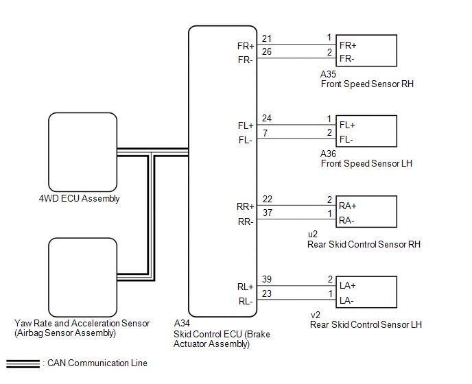
WIRING DIAGRAM
PROCEDURE
| 1. |
CHECK FOR DTC (VEHICLE STABILITY CONTROL SYSTEM) |
(a) Clear the DTC.
Chassis > Brake > Clear DTCs(b) Turn the ignition switch off.
(c) Turn the ignition switch to ON again.
(d) Drive the vehicle, accelerate to a speed of 20 km/h (12 mph) or more, and check if the speed sensor DTC (vehicle stability control system DTC) is output.
Chassis > Brake > Trouble Codes|
Result | Proceed to |
|---|---|
|
Vehicle stability control system DTC (speed sensor or acceleration sensor DTC) is not output |
A |
| Vehicle stability control system DTC (speed sensor or acceleration sensor DTC) is output |
B |
HINT:
When DTCs indicating a CAN communication system malfunction are output, repair the CAN communication system before repairing each corresponding sensor.
| B |
.gif) | REPAIR CIRCUIT INDICATED BY OUTPUT CODE (VEHICLE STABILITY CONTROL SYSTEM)
|
.gif)
|
.gif)
| 2. |
READ VALUE USING TECHSTREAM (WHEEL SPEED) |
(a) Connect the Techstream to the DLC3.
(b) Turn the ignition switch to ON.
(c) Turn the Techstream on.
(d) Enter the following menus: Chassis / Four Wheel Drive / Data List.
(e) Read the value displayed on the Techstream.
Chassis > Four Wheel Drive > Data List|
Tester Display | Measurement Item |
Range | Normal Condition |
Diagnostic Note |
|---|---|---|---|---|
|
FR Wheel Speed | Front wheel speed sensor RH reading |
Min.: 0 km/h (0 mph) Max.: 326 km/h (202 mph) |
0 km/h (0 mph): Vehicle stopped |
No large fluctuations when driving at a constant speed. |
|
FL Wheel Speed | Front wheel speed sensor LH reading |
Min.: 0 km/h (0 mph) Max.: 326 km/h (202 mph) |
0 km/h (0 mph): Vehicle stopped |
No large fluctuations when driving at a constant speed. |
|
RR Wheel Speed | Rear wheel speed sensor RH reading |
Min.: 0 km/h (0 mph) Max.: 326 km/h (202 mph) |
0 km/h (0 mph): Vehicle stopped |
No large fluctuations when driving at a constant speed. |
|
RL Wheel Speed | Rear wheel speed sensor LH reading |
Min.: 0 km/h (0 mph) Max.: 326 km/h (202 mph) |
0 km/h (0 mph): Vehicle stopped |
No large fluctuations when driving at a constant speed. |
|
Tester Display |
|---|
| FR Wheel Speed |
|
FL Wheel Speed |
| RR Wheel Speed |
|
RL Wheel Speed |
OK:
The speed value output from the speed sensor displayed on the Techstream is the same as the actual vehicle speed measured using a speedometer tester (calibrated chassis dynamometer).
| NG | | GO TO VEHICLE STABILITY CONTROL SYSTEM (HOW TO PROCEED WITH TROUBLESHOOTING) |
|
| 3. |
READ VALUE USING TECHSTREAM (FORWARD AND REARWARD G) |
(a) Enter the following menus: Chassis / Four Wheel Drive / Data List.
(b) Read the value displayed on the Techstream.
Chassis > Four Wheel Drive > Data List|
Tester Display | Measurement Item |
Range | Normal Condition |
Diagnostic Note |
|---|---|---|---|---|
|
Forward and Rearward G |
Forward and Rearward G |
Min.: -25.10 m/s2 Max.: 24.90 m/s2 |
Approximately 0 +/-0.13 m/s2 while stationary |
Changes in proportion with acceleration during acceleration/deceleration. |
|
Tester Display |
|---|
| Forward and Rearward G |
OK:
The yaw rate and acceleration sensor (airbag sensor assembly) output value is normal.
| OK | | REPLACE 4WD ECU ASSEMBLY |
| NG | | GO TO VEHICLE STABILITY CONTROL SYSTEM (HOW TO PROCEED WITH TROUBLESHOOTING) |
READ NEXT:
 Steering Angle Sensor (C1297)
DESCRIPTION The 4WD ECU assembly determines that the vehicle is turning based on the signals sent from the steering sensor.
The steering sensor signal is sent to the 4WD ECU assembly via CAN communi
Linear Solenoid Circuit (C1298)
DESCRIPTION The 4WD ECU assembly receives signals from each sensor to control clutch fluid pressure for limiting the center differential operation, which distributes torque according to the driving co
Cancellation of 4WD Control (C1299)
DESCRIPTION This DTC is output if the heat generated by the transmission coupling assembly exceeds a certain amount or if the estimated oil temperature of the transfer exceeds a certain amount while d
SEE MORE:
VEHICLE CONTROL HISTORY (RoB)
VEHICLE CONTROL HISTORY (RoB) DESCRIPTION
Vehicle Control History (RoB) is a function that captures and stores ECU data when triggered by specific vehicle behavior.
It may be possible to determine the cause of the malfunction by checking the vehicle history information and freeze frame dat
FL Speed Sensor Wrong Installation (X0451)
DESCRIPTION
Code Tester Display
Measurement Item Trouble Area
X0451 FL Speed Sensor Wrong Installation
History of front speed sensor LH being installed incorrectly
Front speed sensor LH PROCEDURE
1.
CHECK FOR DTCs (HEALTH CHECK) (a) Perform the H
