Toyota Camry (XV70): Steering Angle Sensor (C1297)
DESCRIPTION
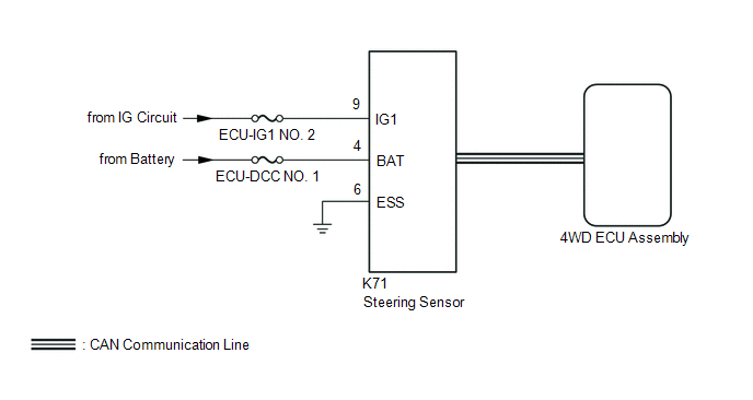
The 4WD ECU assembly determines that the vehicle is turning based on the signals sent from the steering sensor.
The steering sensor signal is sent to the 4WD ECU assembly via CAN communication.
|
DTC No. | Detection Item |
DTC Detection Condition | Trouble Area |
|---|---|---|---|
|
C1297 | Steering Angle Sensor |
When voltage of 4WD ECU assembly IG terminal is 9.5 V or more, and steering sensor malfunction signal is received. |
|
WIRING DIAGRAM
CAUTION / NOTICE / HINT
NOTICE:
Inspect the fuses for circuits related to this system before performing the following inspection procedure.
PROCEDURE
| 1. |
CHECK FOR DTC |
(a) Clear the DTC.
Chassis > Four Wheel Drive > Clear DTCs(b) Turn the ignition switch off.
(c) Turn the ignition switch to ON again and check that no CAN communication system DTC(s) is output.
Click here .gif)
(d) Start the engine.
(e) Drive the vehicle at a speed of 35 km/h (24 mph), turn the steering wheel to the right and left and check that no vehicle stability control system DTC (steering sensor) is output.
Chassis > Brake > Trouble Codes|
Result | Proceed to |
|---|---|
|
Neither CAN communication system DTC nor vehicle stability control system DTC is output |
A |
| CAN communication system DTC is output |
B |
| Vehicle stability control system DTC (steering sensor) is output |
C |
HINT:
When DTCs indicating a CAN communication system malfunction are output, repair the CAN communication system before repairing each corresponding sensor.
| B |
.gif) | GO TO CAN COMMUNICATION SYSTEM (HOW TO PROCEED WITH TROUBLESHOOTING) |
| C |
| REPAIR CIRCUIT INDICATED BY OUTPUT CODE (VEHICLE STABILITY CONTROL SYSTEM)
|
|
.gif)
| 2. |
CHECK HARNESS AND CONNECTOR (POWER SOURCE TERMINAL) |
(a) Remove the steering wheel assembly and the lower steering column cover sub-assembly.
(b) Make sure that there is no looseness at the locking part and the connecting part of the connectors.
| (c) Disconnect the K71 steering sensor connector. |
|
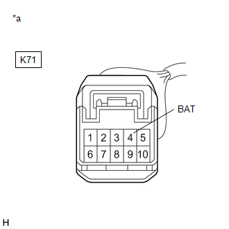
(d) Measure the voltage according to the value(s) in the table below.
Standard Voltage:
|
Tester Connection | Condition |
Specified Condition |
|---|---|---|
|
K71-4 (BAT) - Body ground |
Always | 11 to 14 V |
| NG | | REPAIR OR REPLACE HARNESS OR CONNECTOR |
|
| 3. |
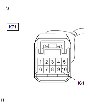
CHECK TERMINAL VOLTAGE (IG1 TERMINAL) |
(a) Turn the ignition switch to ON.
| (b) Measure the voltage according to the value(s) in the table below. |
|
Standard Voltage:
|
Tester Connection | Condition |
Specified Condition |
|---|---|---|
|
K71-9 (IG1) - Body ground |
Ignition switch ON | 11 to 14 V |
| NG | | REPAIR OR REPLACE HARNESS OR CONNECTOR (IG1 CIRCUIT) |
|
| 4. |
CHECK HARNESS AND CONNECTOR (ESS TERMINAL) |
(a) Turn the ignition switch off.
(b) Measure the resistance according to the value(s) in the table below.
Standard Resistance:
|
Tester Connection | Condition |
Specified Condition |
|---|---|---|
|
K71-6 (ESS) - Body ground |
Always | Below 1 Ω |
| NG | | REPAIR OR REPLACE HARNESS OR CONNECTOR |
|
| 5. |
READ VALUE USING TECHSTREAM (STEERING ANGLE VALUE) |
(a) Connect the Techstream to the DLC3.
(b) Turn the ignition switch to ON.
(c) Turn the Techstream on.
(d) Enter the following menus: Chassis / Four Wheel Drive / Data List.
(e) Read the value displayed on the Techstream.
Chassis > Four Wheel Drive > Data List|
Tester Display | Measurement Item |
Range | Normal Condition |
Diagnostic Note |
|---|---|---|---|---|
|
Steering Angle Value | Steering angle value |
Min.: -3276.8 |
READ NEXT:
 Linear Solenoid Circuit (C1298)
DESCRIPTION The 4WD ECU assembly receives signals from each sensor to control clutch fluid pressure for limiting the center differential operation, which distributes torque according to the driving co
Cancellation of 4WD Control (C1299)
DESCRIPTION This DTC is output if the heat generated by the transmission coupling assembly exceeds a certain amount or if the estimated oil temperature of the transfer exceeds a certain amount while d
Diameter of the Tire is not Uniform (C1337)
DESCRIPTION The 4WD ECU assembly outputs this DTC if a difference in tire size is detected.
DTC No. Detection Item
DTC Detection Condition Trouble Area
C1337 Diameter of the T
SEE MORE:
Power outlet
Please use as a power supply for electronic goods that use less than
12 VDC/10 A (power consumption of 120 W).
Open the lid.
■The power outlet can be used when
Vehicles without a smart key system:
The engine switch is in the "ACC" or "ON" position.
Vehicles with a smart key system:
Th
Parking Support Brake
function (static
objects)
If a collision with an object may occur due to the vehicle suddenly
moving forward due to an accidental accelerator pedal
operation, the vehicle moving the unintended direction due to
the wrong shift position being selected, or while parking or traveling
at low speeds, the sensors detect objects
