Toyota Camry (XV70): Back-up Battery
Components
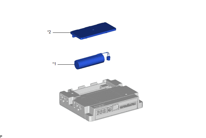
COMPONENTS
ILLUSTRATION
|
*1 | BACK-UP BATTERY |
*2 | TRANSCEIVER COVER |
Removal
REMOVAL
CAUTION / NOTICE / HINT
The necessary procedures (adjustment, calibration, initialization, or registration) that must be performed after parts are removed and installed, or replaced during back-up battery removal/installation are shown below.
Necessary Procedure After Parts Removed/Installed/Replaced|
Replaced Part or Performed Procedure |
Necessary Procedure | Effect/Inoperative Function when Necessary Procedure not Performed |
Link |
|---|---|---|---|
| back-up battery |
Perform the reset back-up battery condition |
Safety connect system |
|
PROCEDURE
1. REMOVE DCM (TELEMATICS TRANSCEIVER) WITH BRACKET
Click here
.gif)
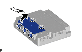
2. REMOVE BACK-UP BATTERY
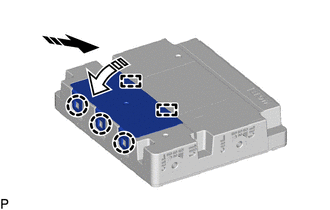
(a) Disengage the 3 claws and 2 guides as shown in the illustration to remove the transceiver cover.
.png) |
Remove in this Direction (1) |
.png) |
Remove in this Direction (2) |
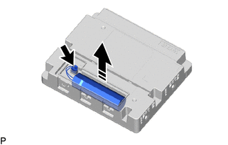
(b) Disconnect the connector.
|
|
Remove in this Direction |
(c) Remove the back-up battery as shown in the illustration.
Installation
INSTALLATION
PROCEDURE
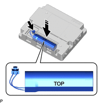
1. INSTALL BACK-UP BATTERY
(a) Connect the connector and install the back-up battery with the "TOP" mark facing upward as shown in the illustration.
.png) |
Install in this Direction |
NOTICE:
Make sure that the connector is connected securely.
(b) Engage the 2 guides and 3 claws as shown in the illustration to install the transceiver cover.
|
|
Install in this Direction (1) |
.png) |
Install in this Direction (2) |
NOTICE:
Make sure that the transceiver cover is securely installed.
2. INSTALL DCM (TELEMATICS TRANSCEIVER) WITH BRACKET
Click here .gif)
3. PERFORM INITIALIZATION
Click here
READ NEXT:
 Components
COMPONENTS ILLUSTRATION
*A for 7 Inch Display
*B for 9 Inch Display
*C w/o Navigation System
*D w/ Navigation System
*1 CENTER INSTRUMENT CLUSTER FINISH
Removal
REMOVAL CAUTION / NOTICE / HINT
The necessary procedures (adjustment, calibration, initialization, or registration) that must be performed after parts are removed and installed, or replaced during D
SEE MORE:
Components
COMPONENTS ILLUSTRATION
*1 BATTERY CLAMP SUB-ASSEMBLY
- -
N*m (kgf*cm, ft.*lbf): Specified torque
- - ILLUSTRATION
*1 FRONT LOWER NO. 1 FLOOR HEAT INSULATOR
- -
N*m (kgf*cm, ft.*lbf): Specified torque
- - ILL
Engine Coolant Temperature Sensor 1 Signal Stuck in Range (P01152A)
DESCRIPTION Refer to DTC P011511. Click here
DTC No. Detection Item
DTC Detection Condition Trouble Area
MIL Memory
Note P01152A
Engine Coolant Temperature Sensor 1 Signal Stuck in Range
Either of the following conditions is met (2 trip detection logic)
