Toyota Camry (XV70): Buzzer does not Sound
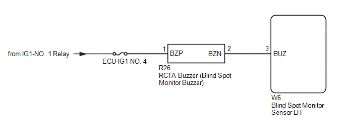
WIRING DIAGRAM
CAUTION / NOTICE / HINT
NOTICE:
- When checking for DTCs, make sure that the blind spot monitor system is turned on.
- Inspect the fuses for circuits related to this system before performing the following procedure.
PROCEDURE
|
1. | CHECK RCTA BUZZER (BLIND SPOT MONITOR BUZZER) |
(a) Check that the RCTA buzzer (blind spot monitor buzzer) sounds when the initial check is performed.
Click here .gif)
OK:
RCTA buzzer sounds
| OK | .gif) | REPLACE BLIND SPOT MONITOR SENSOR LH
|
|
.gif)
| 2. |
CHECK DTC |
(a) Turn the engine switch off.
(b) Turn the engine switch on (IG).
(c) Recheck for DTCs and check if the same DTC is output again.
Body Electrical > Blind Spot Monitor Slave > Trouble CodesOK:
No DTCs are output.
| NG | |
GO TO DTC CHART |
|
| 3. |
CHECK HARNESS AND CONNECTOR (RCTA BUZZER - BLIND SPOT MONITOR SENSOR LH) |
(a) Disconnect the R26 RCTA buzzer (blind spot monitor buzzer) connector.
(b) Measure the voltage according to the value(s) in the table below.
Standard Voltage:
|
Tester Connection | Switch Condition |
Specified Condition |
|---|---|---|
|
R26-1 (BZP) - Body ground |
Engine Switch on (IG) |
11 to 14 V |
|
R26-2 (BZN) or W6-3 (BUZ) - Body ground |
Below 1 V | |
|
R26-2 (BZN) - R26-1 (BZP) |
Below 1 V |
| NG | | REPAIR OR REPLACE HARNESS OR CONNECTOR |
|
| 4. |
CHECK HARNESS AND CONNECTOR (RCTA BUZZER - BLIND SPOT MONITOR SENSOR LH AND BATTERY) |
(a) Disconnect the R26 RCTA buzzer (blind spot monitor buzzer) connector.
(b) Disconnect the W6 blind spot monitor sensor LH connector.
(c) Measure the resistance according to the value(s) in the table below.
Standard Resistance:
|
Tester Connection | Condition |
Specified Condition |
|---|---|---|
|
R26-2 (BZN) - W6-3 (BUZ) |
Always | Below 1 Ω |
|
R26-2 (BZN) or W6-3 (BUZ) - Body ground |
Always | 10 kΩ or higher |
(d) Measure the voltage according to the value(s) in the table below.
Standard Voltage:
|
Tester Connection | Switch Condition |
Specified Condition |
|---|---|---|
|
R26-2 (BZN) or W6-3 (BUZ) - Body ground |
Engine switch on (IG) |
Below 1 V |
|
R26-1 (BZP) - Body ground |
Engine switch on (IG) |
11 to 14 V |
|
R26-1 (BZP) - Body ground |
Engine switch off | Below 1 V |
| OK | | REPLACE BLIND SPOT MONITOR BUZZER
|
| NG | | REPAIR OR REPLACE HARNESS OR CONNECTOR |
READ NEXT:
 Power Source Circuit
DESCRIPTION This circuit provides power to operate the blind spot monitor sensor. WIRING DIAGRAM
CAUTION / NOTICE / HINT
NOTICE: Inspect the fuses for circuits related to this system before perfo
Clearance Warning Buzzer
ComponentsCOMPONENTS ILLUSTRATION
*A for 7 Inch Display
*B for 9 Inch Display
*1 CENTER INSTRUMENT CLUSTER FINISH PANEL ASSEMBLY
*2 CENTER INSTRUMENT CLUSTER FINI
SEE MORE:
Inspection
INSPECTION PROCEDURE 1. INSPECT CAMSHAFT TIMING GEAR BOLT
(a) Check the stroke of the plunger in the center of the camshaft timing gear bolt.
Standard Stroke: 4.5 mm (0.177 in.) or more HINT: When pressing the plunger, there may be a stepped feeling. This is not a malfunction.
If the re
Engine (ignition) switch
(vehicles with a
smart key system)
Performing the following operations when carrying the electronic
key on your person starts the engine or changes engine
switch modes.
Starting the engine
1. Check that the parking brake is set.
2. Check that the shift lever is in P.
3. Firmly depress the brake pedal.
and a message will be di
