Toyota Camry (XV70): Components
COMPONENTS
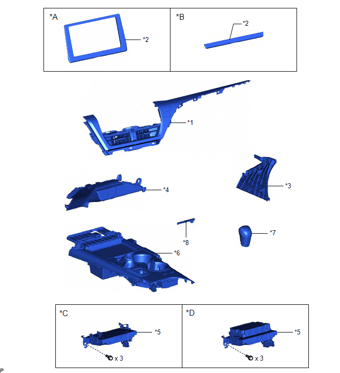
ILLUSTRATION
|
*A | for 7 Inch Display |
*B | for 9 Inch Display |
|
*C | w/o Manual (SOS) Switch |
*D | w/ Manual (SOS) Switch |
|
*1 | CENTER INSTRUMENT CLUSTER FINISH PANEL ASSEMBLY |
*2 | CENTER INSTRUMENT CLUSTER FINISH PANEL SUB-ASSEMBLY |
|
*3 | INSTRUMENT PANEL FINISH PLATE GARNISH |
*4 | LOWER CENTER INSTRUMENT PANEL FINISH PANEL |
|
*5 | NAVIGATION ECU WITH BRACKET |
*6 | REAR UPPER CONSOLE PANEL SUB-ASSEMBLY |
|
*7 | SHIFT LEVER KNOB SUB-ASSEMBLY |
*8 | SHIFT LOCK RELEASE BUTTON COVER |
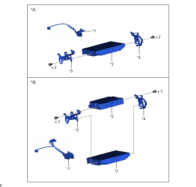
ILLUSTRATION
|
*A | w/o Manual (SOS) Switch |
*B | w/ Manual (SOS) Switch |
|
*1 | ANTENNA CORD SUB-ASSEMBLY |
*2 | DCM (TELEMATICS TRANSCEIVER) |
|
*3 | NAVIGATION ECU |
*4 | NO. 1 TELEPHONE BRACKET |
|
*5 | NO. 2 TELEPHONE BRACKET |
- | - |
READ NEXT:
 Removal
REMOVAL PROCEDURE 1. PRECAUTION
NOTICE:
When replacing the radio and display receiver assembly or navigation ECU, always replace it with a new one. If a radio and display receiver assembly or na
Installation
INSTALLATION PROCEDURE 1. PRECAUTION
NOTICE:
When replacing the radio and display receiver assembly or navigation ECU, always replace it with a new one. If a radio and display receiver assembly
SEE MORE:
Replacement
REPLACEMENT CAUTION / NOTICE / HINT
CAUTION: Do not remove the radiator cap sub-assembly or radiator drain cock plug while the engine and radiator assembly are still hot. Pressurized, hot engine coolant and steam may be released and cause serious burns.
PROCEDURE
1. DRAIN ENGINE COOLANT CAUTI
Components
COMPONENTS ILLUSTRATION
*A for Fold Down Seat Type
- -
*1 REAR SEAT CUSHION ASSEMBLY
*2 REAR SEAT CUSHION LOCK HOOK
*3 REAR SIDE SEATBACK ASSEMBLY LH
*4 REAR CENTER SEAT OUTER BELT ASSEMBLY
*5 REAR SEAT INNER BELT ASSEMBLY RH
*6
© 2023-2025 Copyright www.tocamry.com
