Toyota Camry (XV70): Replacement
REPLACEMENT
CAUTION / NOTICE / HINT
CAUTION:
Do not remove the radiator cap sub-assembly or radiator drain cock plug while the engine and radiator assembly are still hot. Pressurized, hot engine coolant and steam may be released and cause serious burns.
.png)
PROCEDURE
1. DRAIN ENGINE COOLANT
CAUTION:
Do not remove the radiator cap sub-assembly or radiator drain cock plug while the engine and radiator assembly are still hot. Pressurized, hot engine coolant and steam may be released and cause serious burns.
| (a) Remove the 2 screws and clip. |
|
.png)
(b) Pull down the No. 1 engine under cover.
NOTICE:
Do not damage the No. 1 engine under cover.
| (c) Connect a hose with an inside diameter of 8.3 mm (0.327 in.) to the radiator drain cock as shown in the illustration. |
|
.png)
(d) Loosen the radiator drain cock plug.
|
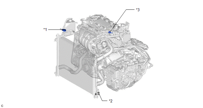
*1 | Radiator Cap Sub-assembly |
*2 | Radiator Drain Cock Plug |
|
*3 | Water Hose Connector (w/ Water Hose Connector) |
- | - |
(e) Remove the radiator cap sub-assembly. Then drain the engine coolant.
HINT:
Collect the engine coolant in a container and dispose of it according to the regulations in your area.
(f) Tighten the radiator drain cock plug by hand.
(g) Disconnect the hose from the radiator drain cock.
(h) Install the 2 screws and clip.
2. ADD ENGINE COOLANT
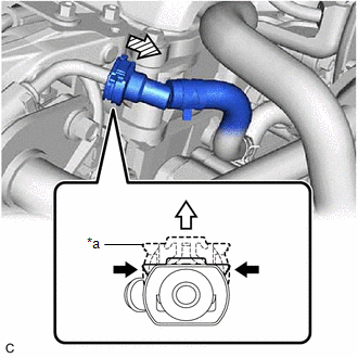
(a) Disconnect the water hose connector from the EGR valve assembly. (w/ Water Hose Connector)
NOTICE:
Remove any foreign matter on the water hose connector and EGR valve pipe before performing this work.
(1) Pinch the retainer of the water hose connector and then pull out the retainer to disengage the lock claws and pull off the water hose connector.
|
*a | Retainer |
.png) |
Pinch |
 |
Pull out |
 |
Pull off |
HINT:
Use a container to catch any engine coolant which flows out of the water hose connector.
(2) Check that there is no foreign matter on the sealing surfaces of the disconnected water lines. Clean them if necessary.
(b) Slowly fill the radiator assembly with engine coolant.
Specified Capacity:
6.9 liters (7.3 US qts, 6.1 Imp. qts)
NOTICE:
Do not substitute plain water for engine coolant.
HINT:
TOYOTA vehicles are filled with TOYOTA SLLC at the factory. In order to avoid damaging the engine cooling system and other technical problems, only use TOYOTA SLLC or similar high quality ethylene glycol based non-silicate, non-amine, non-nitrite, non-borate coolant with long life hybrid organic acid technology (coolant with long-life hybrid organic acid technology is a combination of low phosphates and organic acids).
(c) Remove the reserve tank cap. [*1]
| (d) Slowly pour engine coolant into the radiator reserve tank assembly until it reaches the F line. [*2] NOTICE: Do not substitute plain water for engine coolant. |
|
.png)
(e) Squeeze the No. 1 radiator hose and No. 2 radiator hose several times by hand, and then check the level of the engine coolant.
If the engine coolant level is below the F line, add engine coolant.
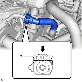
(f) Connect the water hose connector to the EGR valve assembly. (w/ Water Hose Connector)
NOTICE:
Check that there is no damage or foreign matter on the connecting parts of the water lines.
(1) Align the water hose connector with the EGR valve assembly, push the water hose connector onto the EGR valve assembly, then push in the retainer to secure the connection.
|
*a | Retainer |
|
|
Push in |
NOTICE:
Confirm that the retainer makes a "click" sound when pushed.
(2) Check that the water hose connector is securely connected by pulling on it.
(g) Install the radiator cap sub-assembly.
(h) Install the reserve tank cap. [*3]
(i) Perform the following procedure to set the engine to engine coolant filling mode. [*4]
HINT:
It is necessary to set the engine to engine coolant filling mode to ensure that a certain engine water pump assembly (water inlet housing) speed is maintained in order to circulate engine coolant.
(1) Move the shift lever to P.
(2) Start the engine.
(3) Run the engine at 1500 rpm or more for 15 seconds or more.
(4) Check that the speed of the electric water pump increases when the engine is raced to 3000 rpm.
Powertrain > Engine > Data List|
Tester Display |
|---|
| Engine Speed |
|
Electric Water Pump Speed |
Standard:
|
Tester Display | Condition |
Specified Condition |
|---|---|---|
|
Electric Water Pump Speed |
The engine is being raced to 3000 rpm. |
When the engine speed increases, the speed of the electric water pump also increases. |
NOTICE:
Do not move the shift lever from P, or engine coolant filling mode will be canceled.
HINT:
The speed of the engine water pump assembly (water inlet housing) changes in accordance with the engine speed when the engine is being raced in engine coolant filling mode.
(j) Run the engine at 3000 rpm for 10 seconds and then idle the engine for 10 seconds. (Repeat this step at least 3 times.) [*5]
(k) Warm up the engine until the water inlet with thermostat sub-assembly opens. While the water inlet with thermostat sub-assembly is open, circulate the engine coolant for several minutes. [*6]
CAUTION:
- Wear protective gloves.
- Be careful as the No. 2 radiator hose is hot.
- Keep your hands away from the fan.
NOTICE:
- If the coolant temperature gauge indicates an excessive temperature, turn off the engine and let it cool.
- Make sure that the radiator reserve tank assembly still has some engine coolant in it.
- If the radiator reserve tank assembly does not have enough engine coolant, the engine may overheat or be seriously damaged.
- If the radiator reserve tank assembly does not have enough engine coolant, perform the following: 1) stop the engine, 2) wait until the engine coolant has cooled down, and 3) add engine coolant until the radiator reserve tank assembly is filled to the F line.
HINT:
The water inlet with thermostat sub-assembly open timing can be confirmed by squeezing the No. 2 radiator hose by hand, and sensing vibrations when the engine coolant starts to flow inside the No. 2 radiator hose.
(l) Turn the ignition switch off. [*7]
HINT:
Turning off the ignition switch ends engine coolant filling mode.
(m) Wait until the engine coolant cools down. [*8]
(n) Check that the engine coolant level is between the F line and L line. [*9]
HINT:
- If the engine coolant level is below the L line, repeat steps from [*1] to [*9].
- If the engine coolant level is above the F line, drain the engine coolant until the engine coolant level is between the F line and L line.
3. INSPECT FOR COOLANT LEAK
Click here
.gif)
READ NEXT:
 Components
COMPONENTS ILLUSTRATION
*1 NO. 2 ENGINE UNDER COVER ASSEMBLY
*2 V-RIBBED BELT
*3 FRONT WHEEL OPENING EXTENSION PAD LH
*4 FRONT WHEEL OPENING EXTENSION PAD RH
Removal
REMOVAL PROCEDURE 1. REMOVE FRONT WHEEL OPENING EXTENSION PAD RH
Click here
2. REMOVE FRONT WHEEL OPENING EXTENSION PAD LH Click here
3. REMOVE NO. 1 ENGINE UNDER COV
SEE MORE:
Cursor or Map Rotates when Vehicle Stopped
PROCEDURE
1. CHECK CONDITION
(a) Check with the customer if the vehicle has been turned by a turntable.
OK: Vehicle has not been turned by a turntable. HINT:
If the vehicle is turned on a turntable with the engine switch on (IG), the system may store the angular velocity. As
Inspection
INSPECTION PROCEDURE 1. INSPECT BRAKE CYLINDER AND PISTON
(a) Check the rear disc brake cylinder bore and rear disc brake piston for rust and scoring. If necessary, replace the rear disc brake cylinder and rear disc brake piston.
2. INSPECT PAD LINING THICKNESS
(a) Using a ruler, measure t
