Toyota Camry (XV70): Components
COMPONENTS
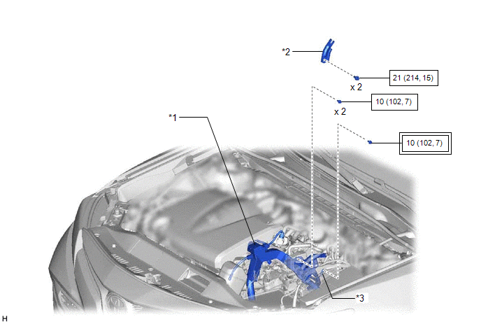
ILLUSTRATION

|
*1 | ENGINE WIRE |
*2 | NO. 2 SURGE TANK STAY |
|
*3 | EARTH WIRE |
- | - |
.png) |
Tightening torque for "Major areas involving basic vehicle performance such as moving/turning/stopping" : N*m (kgf*cm, ft.*lbf) |
.png) |
N*m (kgf*cm, ft.*lbf): Specified torque |
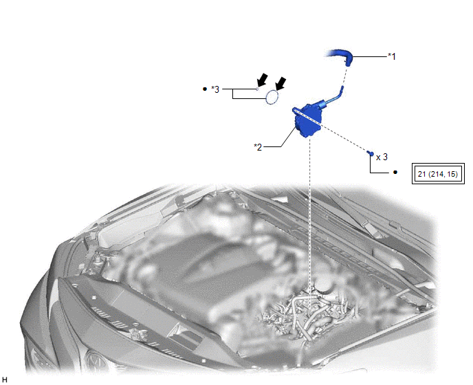
ILLUSTRATION

|
*1 | AIR TUBE |
*2 | VACUUM PUMP ASSEMBLY |
|
*3 | O-RING |
- | - |
.png) |
Tightening torque for "Major areas involving basic vehicle performance such as moving/turning/stopping" : N*m (kgf*cm, ft.*lbf) |
● | Non-reusable part |
.png) |
Engine oil | ★ |
Precoated part |
READ NEXT:
 On-vehicle Inspection
ON-VEHICLE INSPECTION PROCEDURE
1. REMOVE COWL TOP VENTILATOR LOUVER SUB-ASSEMBLY Click here
2. REMOVE FRONT CENTER UPPER SUSPENSION BRACE SUB-ASSEMBLY
Click here
3. OPERATION CHECK (a) S
 Removal
REMOVAL PROCEDURE 1. REMOVE THROTTLE BODY WITH MOTOR ASSEMBLY
Click here 2. REMOVE NO. 2 SURGE TANK STAY
Click here
3. SEPARATE ENGINE WIRE
(a) Remove the 2 bolts and separate the eng
 Installation
INSTALLATION PROCEDURE 1. INSTALL VACUUM PUMP ASSEMBLY
(a) Clean the vacuum pump assembly installation bolt holes in the camshaft housing sub-assembly and cylinder head sub-assembly.
(b) When usin
SEE MORE:
 PCS (Pre-Collision
System)
The pre-collision system uses a radar sensor and front camera
to detect objects in front of the vehicle. When the system
determines that the possibility of a frontal collision with an
object is high, a warning operates to urge the driver to take evasive
action and the potential brake pressure is
 Child restraint system fixed with a child restraint LATCH anchor
■ Child restraint LATCH anchors
LATCH anchors are provided
for the outboard rear seats.
(Marks displaying the location
of the anchors are attached to
the seats.)
■ When installing in the rear outboard seats
Install the child restraint system in accordance to the operation
manual encl
© 2023-2025 Copyright www.tocamry.com

