Toyota Camry (XV70): Components
COMPONENTS
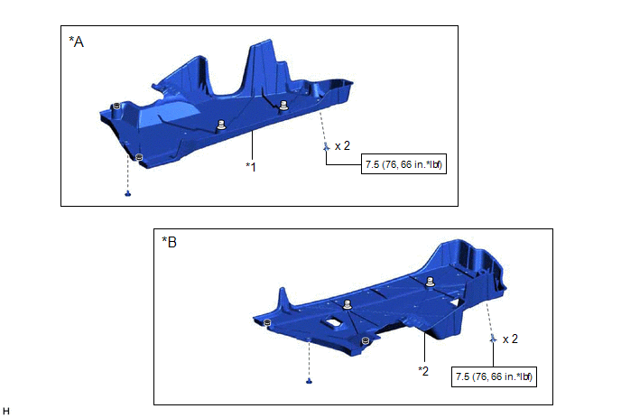
ILLUSTRATION
|
*A | for RH Side |
*B | for LH Side |
|
*1 | NO. 1 FLOOR UNDER COVER |
*2 | NO. 2 FLOOR UNDER COVER |
.png) |
N*m (kgf*cm, ft.*lbf): Specified torque |
- | - |
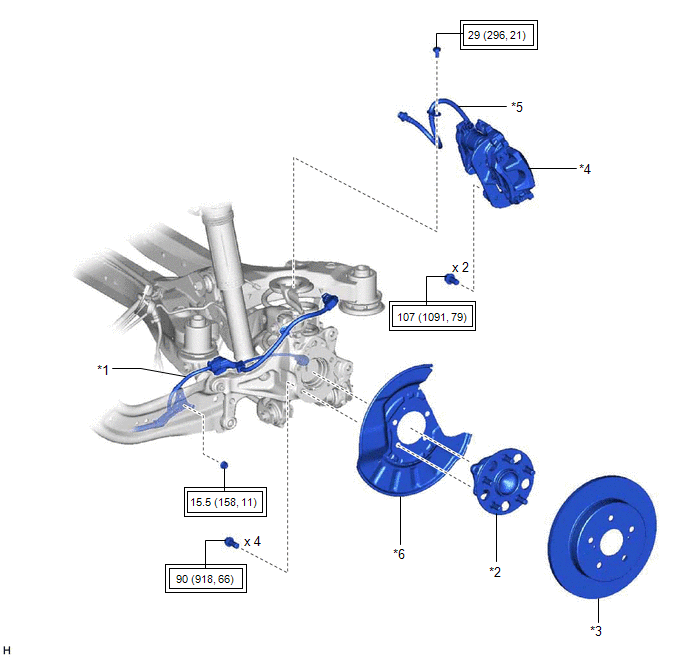
ILLUSTRATION
|
*1 | NO. 2 PARKING BRAKE WIRE ASSEMBLY |
*2 | REAR AXLE HUB AND BEARING ASSEMBLY |
|
*3 | REAR DISC |
*4 | REAR DISC BRAKE CALIPER ASSEMBLY |
|
*5 | REAR FLEXIBLE HOSE |
*6 | REAR DISC BRAKE DUST COVER SUB-ASSEMBLY |
.png) |
Tightening torque for "Major areas involving basic vehicle performance such as moving/turning/stopping": N*m (kgf*cm, ft.*lbf) |
- | - |
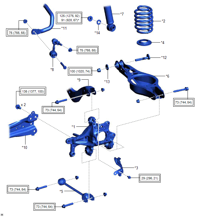
ILLUSTRATION
|
*1 | REAR AXLE CARRIER SUB-ASSEMBLY |
*2 | REAR COIL SPRING |
|
*3 | REAR FLEXIBLE HOSE BRACKET |
*4 | REAR LOWER COIL SPRING INSULATOR |
|
*5 | REAR NO. 1 SUSPENSION ARM ASSEMBLY |
*6 | REAR NO. 2 SUSPENSION ARM ASSEMBLY |
|
*7 | REAR SHOCK ABSORBER ASSEMBLY |
*8 | REAR STABILIZER LINK ASSEMBLY |
|
*9 | REAR UPPER CONTROL ARM ASSEMBLY |
*10 | REAR TRAILING ARM ASSEMBLY |
|
*11 | REAR STABILIZER BAR |
*12 | REAR SUSPENSION TOE ADJUST CAM SUB-ASSEMBLY |
|
*13 | NO. 2 CAMBER ADJUST CAM |
*14 | PLATE WASHER |
|
|
Tightening torque for "Major areas involving basic vehicle performance such as moving/turning/stopping": N*m (kgf*cm, ft.*lbf) |
* | For use with a ball joint lock nut wrench |
READ NEXT:
 Removal
REMOVAL CAUTION / NOTICE / HINT
The necessary procedures (adjustment, calibration, initialization, or registration) that must be performed after parts are removed and installed, or replaced during r
Installation
INSTALLATION CAUTION / NOTICE / HINT
HINT:
Use the same procedure for the RH side and LH side.
The following procedure is for the LH side.
PROCEDURE 1. TEMPORARILY INSTALL REAR AXLE CARR
SEE MORE:
Lost Communication with TCM Missing Message (U010187)
MONITOR DESCRIPTION The engine control unit and the transmission control unit are located inside the ECM. The engine control unit intercommunicates with the transmission control via CAN communication.
If there is a problem in this communication, the ECM store this DTC.
DTC No. Detection It
Operation Method
OPERATION METHOD PROCEDURE 1. PRECAUTION
Click here 2. REMOVE REAR SEAT CUSHION ASSEMBLY
Click here
3. REMOVE REAR SEAT CUSHION LOCK HOOK
Click here
4. PARKING BRAKE FORCED RELEASE
CAUTION: Work on a level surface to ensure safety.
NOTICE:
To release the parking brake, foll
