Toyota Camry (XV70): Components
COMPONENTS
ILLUSTRATION
|
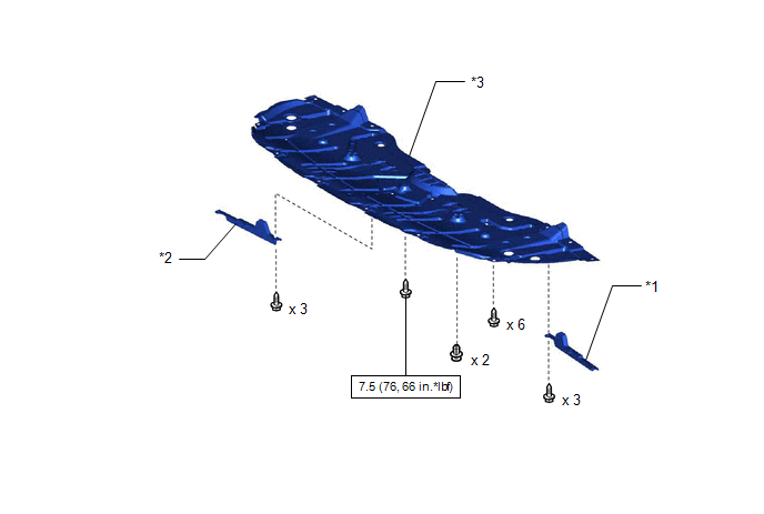
*1 | FRONT WHEEL OPENING EXTENSION PAD LH |
*2 | FRONT WHEEL OPENING EXTENSION PAD RH |
|
*3 | NO. 1 ENGINE UNDER COVER |
- | - |
 |
N*m (kgf*cm, ft.*lbf): Specified torque |
- | - |
ILLUSTRATION
|
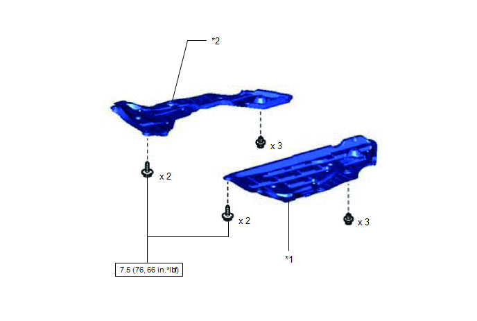
*1 | REAR ENGINE UNDER COVER LH |
*2 | REAR ENGINE UNDER COVER RH |
|
|
N*m (kgf*cm, ft.*lbf): Specified torque |
- | - |
ILLUSTRATION
|
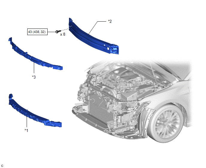
*1 | FRONT BUMPER ENERGY ABSORBER |
*2 | FRONT BUMPER REINFORCEMENT |
|
*3 | NO. 2 FRONT BUMPER ENERGY ABSORBER |
- | - |
|
|
N*m (kgf*cm, ft.*lbf): Specified torque |
- | - |
ILLUSTRATION
|
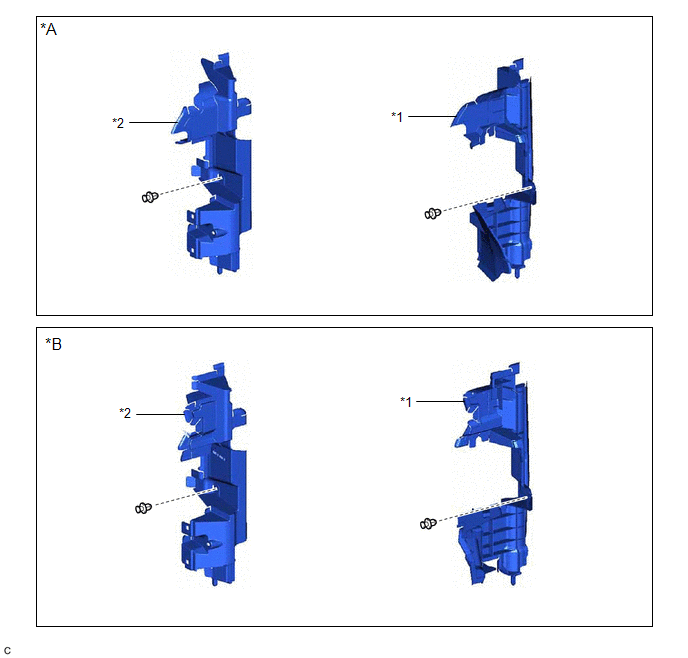
*A | for Bar Type Radiator Grille |
*B | for Mesh Type Radiator Grille |
|
*1 | NO. 1 RADIATOR AIR GUIDE LH |
*2 | NO. 1 RADIATOR AIR GUIDE RH |
ILLUSTRATION
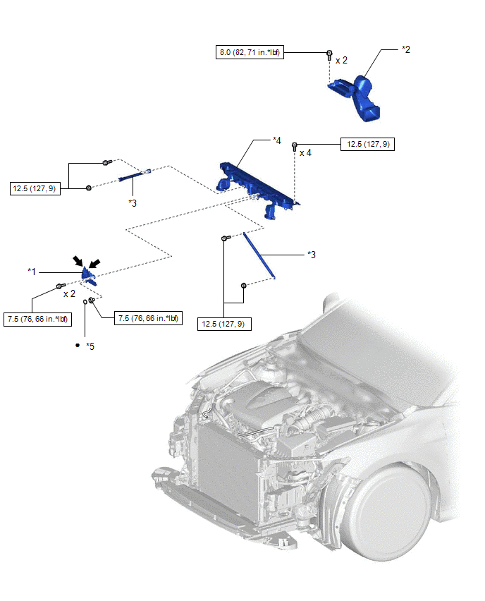
|
*1 | HOOD LOCK ASSEMBLY |
*2 | INLET AIR CLEANER ASSEMBLY |
|
*3 | UPPER RADIATOR MOUNTING BRACKET |
*4 | UPPER RADIATOR SUPPORT SUB-ASSEMBLY |
|
*5 | HOOD LOCK NUT CAP |
- | - |
|
|
N*m (kgf*cm, ft.*lbf): Specified torque |
● | Non-reusable part |
 |
MP grease | - |
- |
ILLUSTRATION
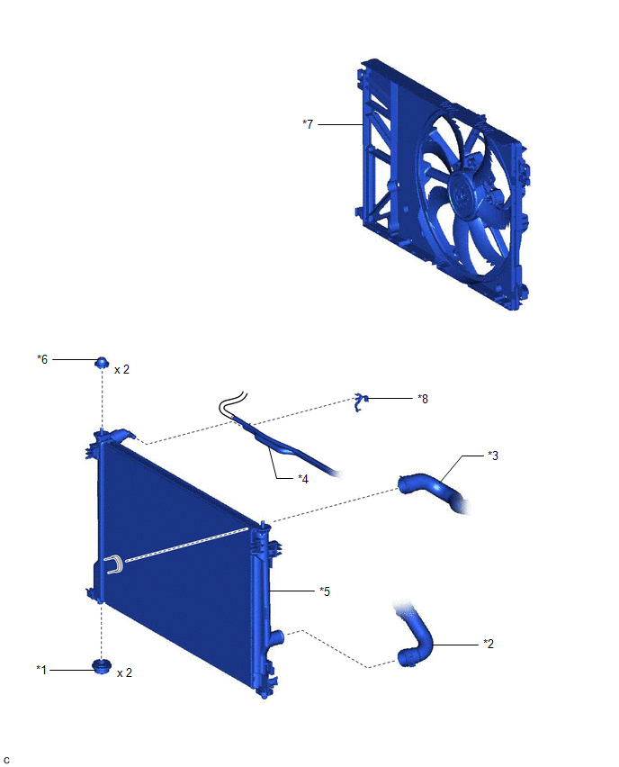
|
*1 | LOWER RADIATOR SUPPORT |
*2 | NO. 1 RADIATOR HOSE |
|
*3 | NO. 2 RADIATOR HOSE |
*4 | NO. 5 WATER BY-PASS HOSE |
|
*5 | RADIATOR ASSEMBLY |
*6 | RADIATOR SUPPORT CUSHION |
|
*7 | FAN SHROUD ASSEMBLY |
*8 | HOSE CLAMP |
READ NEXT:
 On-vehicle Inspection
ON-VEHICLE INSPECTION CAUTION / NOTICE / HINT
CAUTION: Do not remove the radiator cap sub-assembly while the engine and radiator assembly are still hot. Pressurized, hot engine coolant and steam may
Removal
REMOVAL CAUTION / NOTICE / HINT
The necessary procedures (adjustment, calibration, initialization or registration) that must be performed after parts are removed and installed, or replaced during ra
Installation
INSTALLATION PROCEDURE 1. INSTALL LOWER RADIATOR SUPPORT
(a) Install the 2 lower radiator supports to the radiator assembly. 2. INSTALL RADIATOR SUPPORT CUSHION
(a) Install the 2 radiator support
SEE MORE:
Components
COMPONENTS ILLUSTRATION
*1 CLUTCH DRUM OIL SEAL RING
*2 FRONT OIL PUMP BODY
*3 FRONT OIL PUMP DRIVE GEAR
*4 FRONT OIL PUMP DRIVEN GEAR
*5 OIL STRAINER ASSEMBLY
*6 RING PIN
*7 STATOR SHAFT ASSEMBLY
*8 FRONT OIL PUMP COVER SUB-A
Cellular Phone Inspection
PROCEDURE
1. CHECK USAGE CONDITION
(a) Check that the vehicle and cellular phone meet the following conditions:
NOTICE: If changing cellular phone settings, updating software, etc. is necessary, make sure to obtain the permission of the customer before performing it.
The cellula
