Toyota Camry (XV70): Data Signal Circuit between Radio Receiver and Stereo Jack Adapter
DESCRIPTION
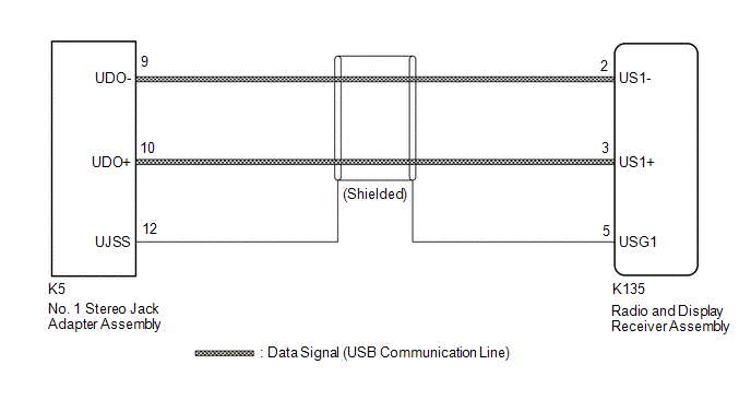
The No. 1 stereo jack adapter assembly sends the sound data signal or image data signal from a USB device to the radio and display receiver assembly via this circuit.
WIRING DIAGRAM
PROCEDURE
| 1. |
CHECK HARNESS AND CONNECTOR (RADIO AND DISPLAY RECEIVER ASSEMBLY - NO. 1 STEREO JACK ADAPTER ASSEMBLY) |
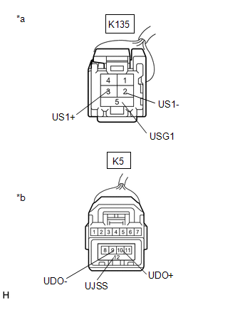
(a) Disconnect the K135 radio and display receiver assembly connector.
(b) Disconnect the K5 No. 1 stereo jack adapter assembly connector.
| (c) Measure the resistance according to the value(s) in the table below. Standard Resistance:
|
|
| OK | .gif) | PROCEED TO NEXT SUSPECTED AREA SHOWN IN PROBLEM SYMPTOMS TABLE
|
.gif)
| NG | | REPAIR OR REPLACE HARNESS OR CONNECTOR |
READ NEXT:
 Mute Signal Circuit between Radio Receiver and Stereo Component Amplifier
DESCRIPTION This circuit sends a signal to the stereo component amplifier assembly to mute noise. Because of that, the noise produced by changing the sound source ceases.
If there is an open in the
Mute Signal Circuit between Stereo Component Amplifier and Telematics Transceiver
DESCRIPTION The DCM (telematics transceiver) sends a mute signal to the stereo component amplifier assembly.
The stereo component amplifier assembly controls the volume according to the mute signal
AVC-LAN Circuit
DESCRIPTION Each unit of the navigation system connected to the AVC-LAN (communication bus) transmits signals via AVC-LAN communication.
If a short to +B or short to ground occurs in an AVC-LAN comm
SEE MORE:
2gr-fks Spark Plug
ComponentsCOMPONENTS ILLUSTRATION
*1 IGNITION COIL ASSEMBLY
*2 SPARK PLUG
*3 V-BANK COVER SUB-ASSEMBLY
*4 VACUUM HOSE
N*m (kgf*cm, ft.*lbf): Specified torque
- - RemovalREMOVAL CAUTION / NOTICE / HINT
The necessary procedures (adjustm
Components
COMPONENTS ILLUSTRATION
*1 REAR DOOR OPENING TRIM WEATHERSTRIP LH
*2 REAR DOOR OPENING TRIM WEATHERSTRIP RH
*3 REAR SEAT CUSHION ASSEMBLY
*4 REAR SEAT CUSHION LOCK HOOK
*5 REAR SEAT OUTER BELT ASSEMBLY LH
*6 REAR SEAT OUTER BELT ASSEMBLY RH
