Toyota Camry (XV70): DCM Data Signal Circuit between Navigation ECU and DCM
DESCRIPTION
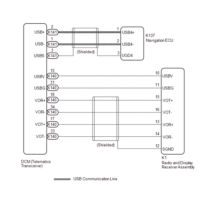
This circuit is used to send and receive signals between the DCM (Telematics Transceiver) and radio and display receiver assembly or navigation ECU.
WIRING DIAGRAM
PROCEDURE
| 1. |
CHECK HARNESS AND CONNECTOR (RADIO AND DISPLAY RECEIVER ASSEMBLY - DCM (TELEMATICS TRANSCEIVER)) |
(a) Disconnect the K140 DCM (Telematics Transceiver) connector.
(b) Disconnect the K1 radio and display receiver assembly connector.
(c) Measure the resistance according to the value(s) in the table below.
Standard Resistance:
|
Tester Connection | Condition |
Specified Condition |
|---|---|---|
|
K140-31 (USBG) - K1-11 (USBG) |
Always | Below 1 Ω |
|
K140-17 (VOT+) - K1-13 (VOR+) |
Always | Below 1 Ω |
|
K140-15 (USBV) - K1-10 (USBV) |
Always | Below 1 Ω |
|
K140-33 (VOT-) - K1-14 (VOR-) |
Always | Below 1 Ω |
|
K140-34 (VOR-) - K1-16 (VOT-) |
Always | Below 1 Ω |
|
K140-18 (VOR+) - K1-15 (VOT+) |
Always | Below 1 Ω |
|
K140-31 (USBG) or K1-11 (USBG) - Body ground |
Always | 10 kΩ or higher |
|
K140-17 (VOT+) or K1-13 (VOR+) - Body ground |
Always | 10 kΩ or higher |
|
K140-15 (USBV) or K1-10 (USBV) - Body ground |
Always | 10 kΩ or higher |
|
K140-33 (VOT-) or K1-14 (VOR-) - Body ground |
Always | 10 kΩ or higher |
|
K140-34 (VOR-) or K1-16 (VOT-) - Body ground |
Always | 10 kΩ or higher |
|
K140-18 (VOR+) or K1-15 (VOT+) - Body ground |
Always | 10 kΩ or higher |
| NG | .gif) | REPAIR OR REPLACE HARNESS OR CONNECTOR |
|
.gif)
| 2. |
CHECK HARNESS AND CONNECTOR (NAVIGATION ECU - DCM (TELEMATICS TRANSCEIVER)) |
| (a) Disconnect the K141 DCM (Telematics Transceiver) connector. |
|
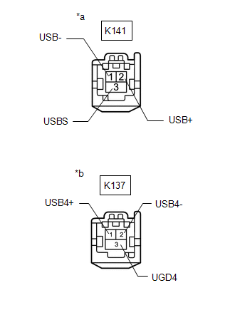
(b) Disconnect the K137 navigation ECU connector.
(c) Measure the resistance according to the value(s) in the table below.
Standard Resistance:
|
Tester Connection | Condition |
Specified Condition |
|---|---|---|
|
K141-1 (USB-) - K137-2 (USB4-) |
Always | Below 1 Ω |
|
K141-2 (USB+) - K137-1 (USB4+) |
Always | Below 1 Ω |
|
K141-3 (USBS) - K137-3(UGD4) |
Always | Below 1 Ω |
|
K141-1 (USB-) or K137-2 (USB4-) - Body ground |
Always | 10 kΩ or higher |
|
K141-2 (USB+) or K137-1 (USB4+) - Body ground |
Always | 10 kΩ or higher |
|
K141-3 (USBS) or K137-3 (UGD4) - Body ground |
Always | 10 kΩ or higher |
| OK | | PROCEED TO NEXT SUSPECTED AREA SHOWN IN PROBLEM SYMPTOMS TABLE |
| NG | | REPAIR OR REPLACE HARNESS OR CONNECTOR |
READ NEXT:
 Parts Location
PARTS LOCATION ILLUSTRATION
*1 INNER REAR VIEW MIRROR ASSEMBLY
- GARAGE DOOR OPENER *2
INSTRUMENT PANEL JUNCTION BLOCK ASSEMBLY - ECU-DCC NO. 2 FUSE
- ECU-IG1 NO. 3 FUSE
SEE MORE:
Removal
REMOVAL PROCEDURE 1. REMOVE FRONT WHEEL OPENING EXTENSION PAD LH
Click here
2. REMOVE FRONT WHEEL OPENING EXTENSION PAD RH Click here
3. REMOVE ENGINE UNDER COVER NO.1
Click here
4. REMOVE ENGINE UNDER COVER REAR LH Click here
5. REMOVE ENGINE UNDER COVER REAR RH
Inside Vehicle
INSIDE VEHICLE
These are maintenance and inspection items that are considered to be the owner's responsibility.
The owner can do them or they can have them done at a service center.
These items include those that should be checked on a daily basis, those that in most cases do not require sp
