Toyota Camry (XV70): Disassembly
DISASSEMBLY
CAUTION / NOTICE / HINT
The necessary procedures (adjustment, calibration, initialization, or registration) that must be performed after parts are removed and installed, or replaced during engine unit removal/installation are shown below.
Necessary Procedure After Parts Removed/Installed/Replaced|
Replaced Part or Performed Procedure |
Necessary Procedure | Effect/Inoperative Function when Necessary Procedure not Performed |
Link |
|---|---|---|---|
| *1: When the ECM is replaced with a new one, reset memory is unnecessary. | |||
| Battery terminal is disconnected/reconnected |
Perform steering sensor zero point calibration |
Lane Tracing Assist System |
|
|
Pre-collision System | |||
|
Memorize steering angle neutral point |
Parking Assist Monitor System |
| |
|
Panoramic view monitor system |
| ||
|
Replacement of ECM | Vehicle Identification Number (VIN) registration |
MIL comes on |
|
|
ECU communication ID registration (Immobiliser system) |
Engine start function |
| |
| Inspection After Repair |
|
|
|
Replacement of automatic transaxle assembly |
|
|
|
|
Replacement of ECM (If possible, read the transaxle compensation code from the previous ECM) |
| ||
| Replacement of ECM (If impossible, read the transaxle compensation code from the previous ECM) |
| ||
| Replacement of ECM |
Code registration |
|
|
|
Replacement of automatic transaxle fluid |
ATF thermal degradation estimate reset |
The value of the Data List item "ATF Thermal Degradation Estimate" is not estimated correctly. |
|
|
Suspension, tires, etc. (The vehicle height changes because of suspension or tire replacement) |
Rear television camera assembly optical axis (Back camera position setting) |
Parking assist monitor system |
|
|
Replacement of front bumper assembly |
Front television camera view adjustment |
Panoramic view monitor system |
|
|
Suspension, tires, etc. (The vehicle height changes because of suspension or tire replacement) |
| ||
| Front wheel alignment adjustment |
|
|
|
.gif)
PROCEDURE
1. REMOVE INTAKE VALVE
|
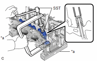
(a) Using SST and wooden blocks, compress the inner compression spring and remove the 6 valve spring retainer locks from the valve spring retainer. SST: 09202-70020 09202-01010 09202-01020 SST: 09202-00021 HINT: Arrange the removed parts in such a way that they can be reinstalled to their original locations. |
|
(b) Remove the 6 valve spring retainers, 6 inner compression springs and 6 intake valves from the cylinder head LH.
HINT:
Arrange the removed parts in such a way that they can be reinstalled to their original locations.
2. REMOVE EXHAUST VALVE
|
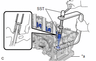
(a) Using SST and wooden blocks, compress the inner compression spring and remove the 6 valve spring retainer locks from the valve spring retainer. SST: 09202-70020 09202-01010 09202-01020 SST: 09202-00021 HINT: Arrange the removed parts in such a way that they can be reinstalled to their original locations. |
|
(b) Remove the 6 valve spring retainers, 6 inner compression springs and 6 exhaust valves from the cylinder head LH.
HINT:
Arrange the removed parts in such a way that they can be reinstalled to their original locations.
3. REMOVE INTAKE VALVE STEM OIL SEAL
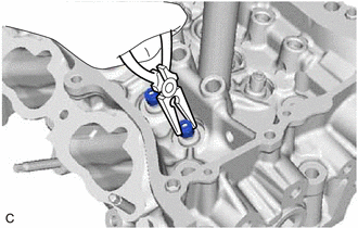
| (a) Using needle-nose pliers, remove the 6 intake valve stem oil seals from the intake valve guide bush. |
|
4. REMOVE EXHAUST VALVE STEM OIL SEAL
HINT:
Use the same procedure as for the intake side.
5. REMOVE VALVE SPRING SEAT
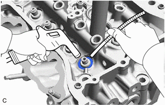
| (a) Using compressed air and a Magnet Hand, remove the 12 valve spring seats by blowing air onto them from the cylinder head LH. HINT: Arrange the removed parts in such a way that they can be reinstalled to their original locations. |
|
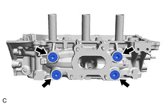
6. REMOVE NO. 1 STRAIGHT SCREW PLUG
NOTICE:
If coolant leaks from a No. 1 straight screw plug or a plug is corroded, replace it.
| (a) Using a 10 mm hexagon socket wrench, remove the 2 No. 1 straight screw plugs and 2 water hole gaskets from the cylinder head LH. |
|
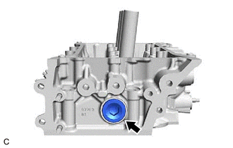
7. REMOVE NO. 2 STRAIGHT SCREW PLUG
NOTICE:
If coolant leaks from a No. 2 straight screw plug or a plug is corroded, replace it.
| (a) Using a 14 mm hexagon wrench, remove the No. 2 straight screw plug and cylinder head screw plug gasket from the cylinder head LH. |
|
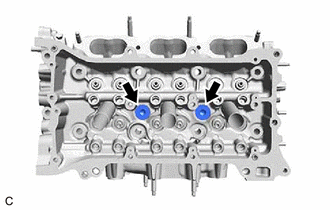
8. REMOVE NO. 3 STRAIGHT SCREW PLUG
NOTICE:
If coolant leaks from a No. 3 straight screw plug or a plug is corroded, replace it.
| (a) Using a 10 mm hexagon socket wrench, remove the 4 No. 3 straight screw plugs and 4 cylinder head screw plug gaskets from the cylinder head LH. |
|
READ NEXT:
 Inspection
INSPECTION CAUTION / NOTICE / HINT
HINT:
Use the same procedure for bank 1 and bank 2.
The following procedure is for bank 2.
PROCEDURE 1. INSPECT CYLINDER HEAD LH (a) Using a precision
Replacement
REPLACEMENT CAUTION / NOTICE / HINT
HINT:
Use the same procedure for bank 1 and bank 2.
The following procedure is for bank 2.
PROCEDURE 1. REPLACE INTAKE VALVE GUIDE BUSH
(a) Heat the
Reassembly
REASSEMBLY CAUTION / NOTICE / HINT
HINT:
Use the same procedure for bank 1 and bank 2.
The following procedure is for bank 2.
PROCEDURE 1. INSTALL SPARK PLUG TUBE HINT:
When using a ne
SEE MORE:
Removal
REMOVAL CAUTION / NOTICE / HINT
The necessary procedures (adjustment, calibration, initialization or registration) that must be performed after parts are removed and installed, or replaced during shift paddle switch (transmission shift switch assembly) removal/installation are shown below. Necessa
Rear Brake Flexible Hose(w/ Electric Parking Brake System)
ComponentsCOMPONENTS ILLUSTRATION
*1 REAR FLEXIBLE HOSE
*2 GASKET
*3 UNION BOLT
*4 BRAKE LINE
Tightening torque for "Major areas involving basic vehicle performance such as moving/turning/stopping" : N*m (kgf*cm, ft.*lbf)
* For use with a
