Toyota Camry (XV70): Removal
REMOVAL
CAUTION / NOTICE / HINT
The necessary procedures (adjustment, calibration, initialization or registration) that must be performed after parts are removed and installed, or replaced during shift paddle switch (transmission shift switch assembly) removal/installation are shown below.
Necessary Procedures After Parts Removed/Installed/Replaced|
Replaced Part or Performed Procedure |
Necessary Procedure | Effect/Inoperative Function when Necessary Procedure not Performed |
Link |
|---|---|---|---|
|
Battery terminal is disconnected/reconnected |
Perform steering sensor zero point calibration |
Lane Tracing Assist System |
|
|
Pre-collision system | |||
|
Memorize steering angle neutral point |
Parking assist monitor system |
| |
|
Panoramic view monitor system |
|
NOTICE:
- Do not remove/install the spiral cable with sensor sub-assembly with the battery connected and the ignition switch ON.
- Do not rotate the spiral cable with sensor sub-assembly without the steering wheel assembly installed, with the battery connected and the ignition switch ON.
- Ensure that the steering wheel assembly is installed and aligned straight when inspecting the steering sensor.
PROCEDURE
1. REMOVE STEERING WHEEL ASSEMBLY
Click here .gif)
2. REMOVE STEERING PAD SWITCH ASSEMBLY
Click here
3. REMOVE SHIFT PADDLE SWITCH (TRANSMISSION SHIFT SWITCH ASSEMBLY)
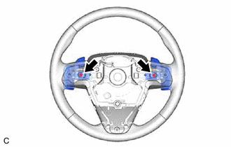
| (a) Remove the 2 screws. |
|
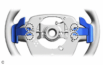
| (b) Disengage the 4 claws. |
|
| (c) Disengage the 2 clamps to disconnect the 2 shift paddle switches (transmission shift switch assemblies) from the steering wheel assembly. |
|
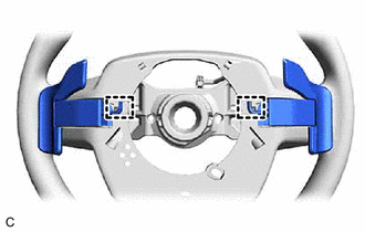
| (d) Disconnect the 2 shift paddle switch (transmission shift switch assembly) connectors to remove the 2 shift paddle switches (transmission shift switch assemblies) from the No. 1 switch wire. |
|
4. REMOVE NO. 1 SWITCH WIRE
HINT:
Perform this procedure only when replacement of the No. 1 switch wire is necessary.
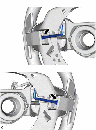
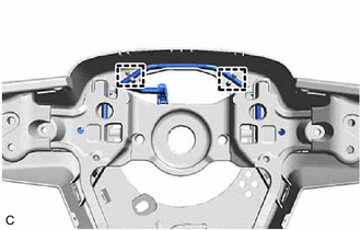
| (a) Disengage the 2 guides and remove the No. 1 switch wire from the steering wheel assembly. |
|
READ NEXT:
 Inspection
INSPECTION PROCEDURE 1. INSPECT SHIFT PADDLE SWITCH (TRANSMISSION SHIFT SWITCH ASSEMBLY)
(a) Shift Paddle Switch LH (Transmission Shift Switch Assembly):
(1) Measure the resistance according t
Installation
INSTALLATION PROCEDURE 1. INSTALL NO. 1 SWITCH WIRE
HINT: Perform this procedure only when replacement of the No. 1 switch wire is necessary.
(a) Engage the 2 guides to install the No. 1 switch wi
Speed Sensor
ComponentsCOMPONENTS ILLUSTRATION
*1 TRANSMISSION REVOLUTION SENSOR (NC)
*2 TRANSMISSION REVOLUTION SENSOR (NT)
*3 SPACER
- -
Tightening torque for
SEE MORE:
Stop Lamp Relay Actuator Stuck On (C13807E)
DESCRIPTION When any of the following conditions are met, the skid control ECU (brake actuator assembly) sets the drive output (STPO) ON which operates the stop light control relay (stop light switch assembly) and turns on the stop lights. Illumination Conditions:
Pre-collision brake is operati
Illumination Circuit
DESCRIPTION Power is supplied to the radio and display receiver assembly and steering pad switch assembly illumination when the light control switch is in the tail or head position. WIRING DIAGRAM
CAUTION / NOTICE / HINT
NOTICE:
The vehicle is equipped with a Supplemental Restraint System (
