Toyota Camry (XV70): Speed Sensor
Components
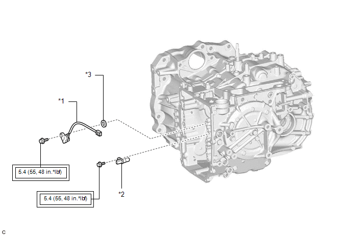
COMPONENTS
ILLUSTRATION
|
*1 | TRANSMISSION REVOLUTION SENSOR (NC) |
*2 | TRANSMISSION REVOLUTION SENSOR (NT) |
|
*3 | SPACER |
- | - |
.png) |
Tightening torque for "Major areas involving basic vehicle performance such as moving/turning/stopping": N*m (kgf*cm, ft.*lbf) |
- | - |
Removal
REMOVAL
CAUTION / NOTICE / HINT
The necessary procedures (adjustment, calibration, initialization or registration) that must be performed after parts are removed and installed, or replaced during transmission revolution sensor (NT) and transmission revolution sensor (NC) removal/installation are shown below.
Necessary Procedures After Parts Removed/Installed/Replaced|
Replaced Part or Performed Procedure |
Necessary Procedure | Effect/Inoperative Function when Necessary Procedure not Performed |
Link |
|---|---|---|---|
| Replacement of automatic transaxle fluid |
ATF thermal degradation estimate reset |
The value of the Data List item "ATF Thermal Degradation Estimate" is not estimated correctly. |
|
|
Transmission valve body assembly |
|
|
|
PROCEDURE
1. REMOVE TRANSMISSION VALVE BODY ASSEMBLY
Click here
.gif)
2. REMOVE TRANSMISSION REVOLUTION SENSOR (NT)
| (a) Remove the bolt and transmission revolution sensor (NT) from the automatic transaxle case sub-assembly. |
|
.png)
3. REMOVE TRANSMISSION REVOLUTION SENSOR (NC)
| (a) Remove the bolt, spacer and transmission revolution sensor (NC) from the counter drive gear sub-assembly. |
|
.png)
Installation
INSTALLATION
PROCEDURE
1. INSTALL TRANSMISSION REVOLUTION SENSOR (NC)
(a) Install the transmission revolution sensor (NC) and spacer to the counter drive gear sub-assembly with the bolt.
Torque:
5.4 N
READ NEXT:
 Torque Converter And Drive Plate
InspectionINSPECTION PROCEDURE
1. INSPECT TORQUE CONVERTER ASSEMBLY (a) Inspect the one-way clutch. Press on the splines of the stator with a finger and rotate it. Check that it rotates smoothly whe
Components
COMPONENTS ILLUSTRATION
*1 BATTERY CLAMP SUB-ASSEMBLY
- -
N*m (kgf*cm, ft.*lbf): Specified torque
- - ILLUSTRATION
*1 FRONT LOWER NO. 1 FLOOR
SEE MORE:
Dtc Check / Clear
DTC CHECK / CLEAR CHECK DTC AND FREEZE FRAME DATA (USING TECHSTREAM)
(a) Turn the ignition switch off. (b) Connect the Techstream to the DLC3.
(c) Turn the ignition switch to ON. (d) Turn the Techstream on.
(e) Enter the following menus: Chassis / Brake/EPB / Trouble Codes. Chassis > Brake
Front Wiper Rubber
ComponentsCOMPONENTS ILLUSTRATION
*1 FRONT WIPER BLADE
*2 WIPER RUBBER
*3 FRONT WIPER RUBBER BACKING PLATE
- - RemovalREMOVAL CAUTION / NOTICE / HINT
NOTICE: Make sure to hold the front wiper arm while lifting it as lifting the front wiper arm by the front
