Toyota Camry (XV70): Illumination Circuit
DESCRIPTION
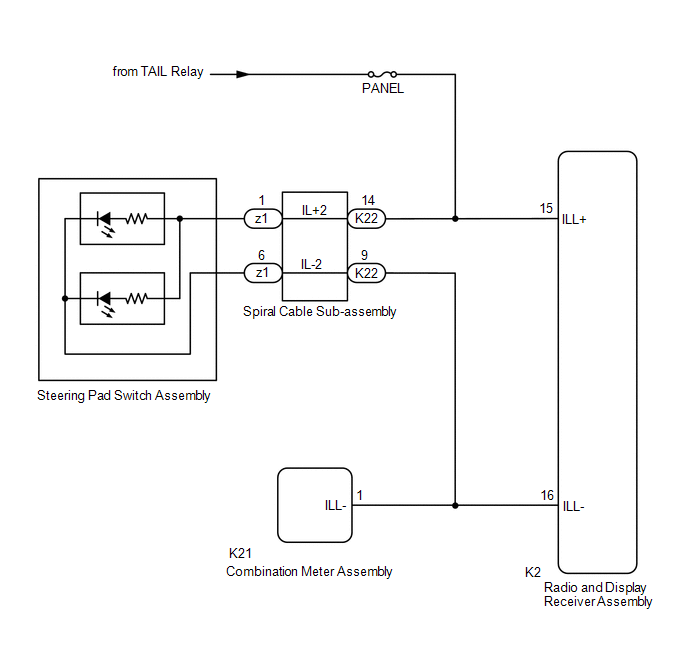
Power is supplied to the radio and display receiver assembly and steering pad switch assembly illumination when the light control switch is in the tail or head position.
WIRING DIAGRAM
CAUTION / NOTICE / HINT
NOTICE:
- The vehicle is equipped with a Supplemental Restraint System (SRS) which includes components such as airbags. Before servicing (including removal or installation of parts), be sure to read the precaution for Supplemental Restraint System.
Click here
.gif)
- Inspect the fuses for circuits related to this system before performing the following procedure.
PROCEDURE
|
1. | CHECK ILLUMINATION |
(a) Check if the illumination for the radio and display receiver assembly, steering pad switch assembly, heater control switch or others (hazard switch, transmission control switch, etc.) comes on when the light control switch is turned to the head or tail position.
|
Result | Proceed to |
|---|---|
|
Illumination comes on for all components except steering pad switch assembly. |
A |
| Illumination comes on for all components except radio and display receiver assembly. |
B |
| No illumination comes on (radio and display receiver assembly, hazard switch, heater control switch, etc.). |
C |
| B |
.gif) | GO TO STEP 5 |
| C |
| GO TO LIGHTING SYSTEM |
|
.gif)
| 2. |
CHECK HARNESS AND CONNECTOR (ILLUMINATION SIGNAL) |
(a) Disconnect the K22 spiral cable sub-assembly connector.
(b) Measure the voltage according to the value(s) in the table below.
Standard Voltage:
|
Tester Connection | Condition |
Specified Condition |
|---|---|---|
|
K22-14 (IL+2) - Body ground |
Light control switch in tail or head position |
11 to 14 V |
| NG | | REPAIR OR REPLACE HARNESS OR CONNECTOR |
|
| 3. |
INSPECT STEERING PAD SWITCH ASSEMBLY |
(a) Remove the steering pad switch assembly.
Click here
(b) Inspect the steering pad switch assembly.
Click here
| NG | | REPLACE STEERING PAD SWITCH ASSEMBLY
|
|
| 4. |
INSPECT SPIRAL CABLE SUB-ASSEMBLY |
(a) Remove the spiral cable sub-assembly.
Click here
(b) Inspect the spiral cable sub-assembly.
Click here
| OK | | REPAIR OR REPLACE HARNESS OR CONNECTOR (SPIRAL CABLE SUB-ASSEMBLY - RADIO AND DISPLAY RECEIVER ASSEMBLY, COMBINATION METER ASSEMBLY) |
| NG | | REPLACE SPIRAL CABLE SUB-ASSEMBLY
|
| 5. |
CHECK HARNESS AND CONNECTOR (ILLUMINATION SIGNAL) |
(a) Disconnect the K2 radio and display receiver assembly connector.
(b) Measure the voltage according to the value(s) in the table below.
Standard Voltage:
|
Tester Connection | Condition |
Specified Condition |
|---|---|---|
|
K2-15 (ILL+) - Body ground |
Light control switch in tail or head position |
11 to 14 V |
| NG | | REPAIR OR REPLACE HARNESS OR CONNECTOR |
|
| 6. |
CHECK HARNESS AND CONNECTOR (RADIO AND DISPLAY RECEIVER ASSEMBLY - COMBINATION METER ASSEMBLY) |
(a) Disconnect the K2 radio and display receiver assembly connector.
(b) Disconnect the K21 combination meter assembly connector.
(c) Measure the resistance according to the value(s) in the table below.
Standard Resistance:
|
Tester Connection | Condition |
Specified Condition |
|---|---|---|
|
K2-16 (ILL-) - K21-1 (ILL-) |
Always | Below 1 Ω |
|
K2-16 (ILL-) or K21-1 (ILL-) - Body ground |
Always | 10 kΩ or higher |
| OK | | PROCEED TO NEXT SUSPECTED AREA SHOWN IN PROBLEM SYMPTOMS TABLE
|
| NG | | REPAIR OR REPLACE HARNESS OR CONNECTOR |
READ NEXT:
 Parking Brake Switch Circuit
DESCRIPTION This circuit is from the parking brake switch assembly*1 or skid control ECU (Brake Actuator Assembly)*2 to the radio and display receiver assembly.
*1: w/o Electric Parking Brake Sys
Speaker Circuit
DESCRIPTION for 6 Speakers
If there is a short in a speaker circuit, the radio and display receiver assembly detects it and stops output to the speakers.
Thus sound cannot be heard from the spe
Sound Signal Circuit between Radio Receiver and Stereo Component Amplifier
DESCRIPTION The radio and display receiver assembly sends a sound signal to the stereo component amplifier assembly via this circuit.
The sound signal that is sent is amplified by the stereo compone
SEE MORE:
Certification ECU Vehicle Information Reading/Writing Process Malfunction (B15F7)
DESCRIPTION This DTC may be stored when items controlled by the certification ECU (smart key ECU assembly) cannot be customized via the navigation system vehicle customization screen.
HINT: The certification ECU (smart key ECU assembly) controls the smart key system related items that are customiz
Pressure Control Solenoid "A" Circuit Short to Battery (P074512)
DESCRIPTION Changing gears is performed by the ECM turning the solenoid (SL1, SL2, SL3, SL4, SL5 and SL6) valves on and off.
If an open or short occurs in any of the solenoid valve circuits, the ECM controls the remaining normal solenoid valves to allow the vehicle to be driven. If all of the sole
