Toyota Camry (XV70): Sound Signal Circuit between Radio Receiver and Stereo Component Amplifier
DESCRIPTION
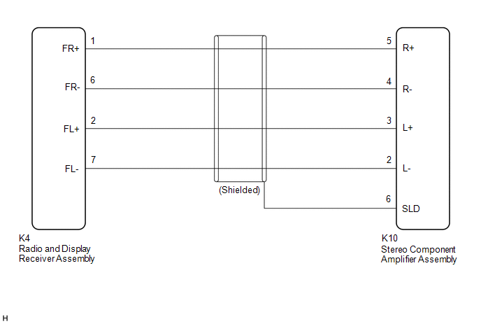
The radio and display receiver assembly sends a sound signal to the stereo component amplifier assembly via this circuit.
The sound signal that is sent is amplified by the stereo component amplifier assembly, and then is sent to the speakers.
If there is an open or short in this circuit, sound cannot be heard from the speakers even if the stereo component amplifier assembly or speakers are not malfunctioning.
WIRING DIAGRAM
PROCEDURE
| 1. |
CHECK HARNESS AND CONNECTOR (RADIO AND DISPLAY RECEIVER ASSEMBLY - STEREO COMPONENT AMPLIFIER ASSEMBLY) |
(a) Disconnect the K4 radio and display receiver assembly connector.
(b) Disconnect the K10 stereo component amplifier assembly connector.
(c) Measure the resistance according to the value(s) in the table below.
Standard Resistance:
|
Tester Connection | Condition |
Specified Condition |
|---|---|---|
|
K10-5 (R+) - K4-1 (FR+) |
Always | Below 1 Ω |
|
K10-4 (R-) - K4-6 (FR-) |
Always | Below 1 Ω |
|
K10-3 (L+) - K4-2 (FL+) |
Always | Below 1 Ω |
|
K10-2 (L-) - K4-7 (FL-) |
Always | Below 1 Ω |
|
K10-6 (SLD) - Body ground |
Always | 10 kΩ or higher |
|
K10-5 (R+) or K4-1 (FR+) - Body ground |
Always | 10 kΩ or higher |
|
K10-4 (R-) or K4-6 (FR-) - Body ground |
Always | 10 kΩ or higher |
|
K10-3 (L+) or K4-2 (FL+) - Body ground |
Always | 10 kΩ or higher |
|
K10-2 (L-) or K4-7 (FL-) - Body ground |
Always | 10 kΩ or higher |
| OK | .gif) | PROCEED TO NEXT SUSPECTED AREA SHOWN IN PROBLEM SYMPTOMS TABLE
|
.gif)
| NG | | REPAIR OR REPLACE HARNESS OR CONNECTOR |
READ NEXT:
 Data Signal Circuit between Radio Receiver and Stereo Jack Adapter
DESCRIPTION The No. 1 stereo jack adapter assembly sends the sound data signal or image data signal from a USB device to the radio and display receiver assembly via this circuit. WIRING DIAGRAM
PRO
Mute Signal Circuit between Radio Receiver and Stereo Component Amplifier
DESCRIPTION This circuit sends a signal to the stereo component amplifier assembly to mute noise. Because of that, the noise produced by changing the sound source ceases.
If there is an open in the
Mute Signal Circuit between Stereo Component Amplifier and Telematics Transceiver
DESCRIPTION The DCM (telematics transceiver) sends a mute signal to the stereo component amplifier assembly.
The stereo component amplifier assembly controls the volume according to the mute signal
SEE MORE:
Power outlet
Please use as a power supply for electronic goods that use less than
12 VDC/10 A (power consumption of 120 W).
Open the lid.
■The power outlet can be used when
Vehicles without a smart key system:
The engine switch is in the "ACC" or "ON" position.
Vehicles with a smart key system:
Th
Removal
REMOVAL CAUTION / NOTICE / HINT
The necessary procedures (adjustment, calibration, initialization or registration) that must be performed after parts are removed and installed, or replaced during brake pedal support assembly removal/installation are shown below. Necessary Procedures After Parts Re
