Toyota Camry (XV70): Mute Signal Circuit between Radio Receiver and Stereo Component Amplifier
DESCRIPTION
This circuit sends a signal to the stereo component amplifier assembly to mute noise. Because of that, the noise produced by changing the sound source ceases.
If there is an open in the circuit, noise can be heard from the speakers when changing the sound source.
If there is a short in the circuit, even though the stereo component amplifier assembly is functioning normally, no sound or only an extremely faint sound can be heard.
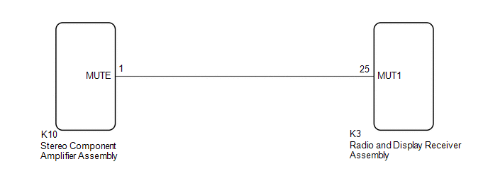
WIRING DIAGRAM
CAUTION / NOTICE / HINT
NOTICE:
- Depending on the parts that are replaced during vehicle inspection or maintenance, performing initialization, registration or calibration may be needed. Refer to Precaution for Audio and Visual System.
Click here
.gif)
- When replacing the radio and display receiver assembly, always replace it with a new one. If a radio and display receiver assembly which was installed to another vehicle is used, the following may occur:
- A communication malfunction DTC may be stored.
- The radio and display receiver assembly may not operate normally.
PROCEDURE
|
1. | INSPECT STEREO COMPONENT AMPLIFIER ASSEMBLY |
| (a) Measure the voltage according to the value(s) in the table below. Standard Voltage:
|
|
| OK | .gif) | PROCEED TO NEXT SUSPECTED AREA SHOWN IN PROBLEM SYMPTOMS TABLE
|
|
.gif)
| 2. |
CHECK HARNESS AND CONNECTOR (RADIO AND DISPLAY RECEIVER ASSEMBLY - STEREO COMPONENT AMPLIFIER ASSEMBLY) |
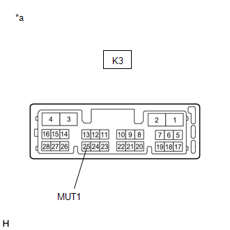
(a) Disconnect the K3 radio and display receiver assembly connector.
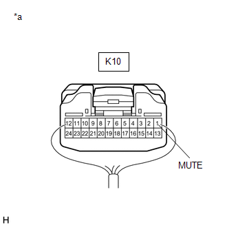
(b) Disconnect the K10 stereo component amplifier assembly connector.
(c) Measure the resistance according to the value(s) in the table below.
Standard Resistance:
|
Tester Connection | Condition |
Specified Condition |
|---|---|---|
|
K3-25 (MUT1) - K10-1 (MUTE) |
Always | Below 1 Ω |
|
K3-25 (MUT1) or K10-1 (MUTE) - Body ground |
Always | 10 kΩ or higher |
| NG | | REPAIR OR REPLACE HARNESS OR CONNECTOR |
|
| 3. |
INSPECT STEREO COMPONENT AMPLIFIER ASSEMBLY (OUTPUT SIGNAL) |
(a) Reconnect the K10 stereo component amplifier assembly connector.
(b) Disconnect the K3 radio and display receiver assembly connector.
| (c) Measure the voltage according to the value(s) in the table below. Standard Voltage:
|
|
| OK | | REPLACE RADIO AND DISPLAY RECEIVER ASSEMBLY
|
| NG | | REPLACE STEREO COMPONENT AMPLIFIER ASSEMBLY
|
READ NEXT:
 Mute Signal Circuit between Stereo Component Amplifier and Telematics Transceiver
DESCRIPTION The DCM (telematics transceiver) sends a mute signal to the stereo component amplifier assembly.
The stereo component amplifier assembly controls the volume according to the mute signal
Mute Signal Circuit between Radio Receiver and Telematics Transceiver
DESCRIPTION The DCM (telematics transceiver) sends a mute signal to the radio and display receiver assembly.
The radio and display receiver assembly controls the volume according to the mute signal
AVC-LAN Circuit
DESCRIPTION Each unit of the audio and visual system connected to the AVC-LAN (communication bus) transmits signals via AVC-LAN communication.
If a short to +B or short to ground occurs in an AVC-LA
SEE MORE:
Diagnostic Trouble Code Chart
DIAGNOSTIC TROUBLE CODE CHART Vehicle Stability Control System
DTC No. Detection Item
Link C00631C
Yaw Rate Sensor Circuit Voltage Out of Range
C00631F Yaw Rate Sensor Circuit Intermittent
C006396 Yaw Rate Sensor Component Internal Failure
Components
COMPONENTS ILLUSTRATION
*1 NO. 2 PARKING BRAKE WIRE ASSEMBLY
*2 REAR AXLE HUB AND BEARING ASSEMBLY
*3 REAR DISC
*4 REAR DISC BRAKE CALIPER ASSEMBLY
*5 REAR FLEXIBLE HOSE
*6 REAR DISC BRAKE DUST COVER SUB-ASSEMBLY
Tightening torqu
