Toyota Camry (XV70): AVC-LAN Circuit
DESCRIPTION
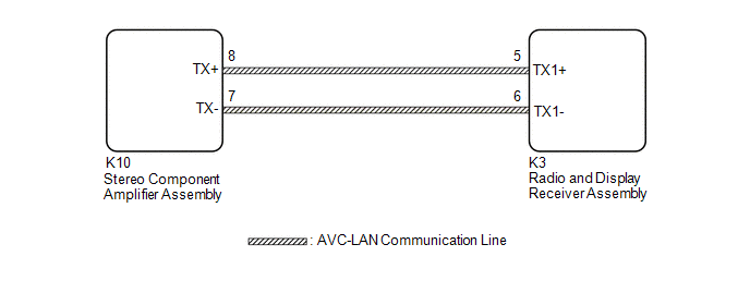
Each unit of the audio and visual system connected to the AVC-LAN (communication bus) transmits signals via AVC-LAN communication.
If a short to +B or short to ground occurs in an AVC-LAN communication line, the audio and visual system will not function normally because communication is not possible.
WIRING DIAGRAM
CAUTION / NOTICE / HINT
HINT:
The radio and display receiver assembly is the master unit.
NOTICE:
- Depending on the parts that are replaced during vehicle inspection or maintenance, performing initialization, registration or calibration may be needed. Refer to Precaution for Audio and Visual System.
Click here
.gif)
- When replacing the radio and display receiver assembly, always replace it with a new one. If a radio and display receiver assembly which was installed to another vehicle is used, the following may occur:
- A communication malfunction DTC may be stored.
- The radio and display receiver assembly may not operate normally.
PROCEDURE
|
1. | INSPECT RADIO AND DISPLAY RECEIVER ASSEMBLY |
(a) Remove the radio and display receiver assembly.
| (b) Measure the resistance according to the value(s) in the table below. Standard Resistance:
|
|
| NG | .gif) | REPLACE RADIO AND DISPLAY RECEIVER ASSEMBLY
|
|
.gif)
| 2. |
CHECK HARNESS AND CONNECTOR (AVC-LAN CIRCUIT) |
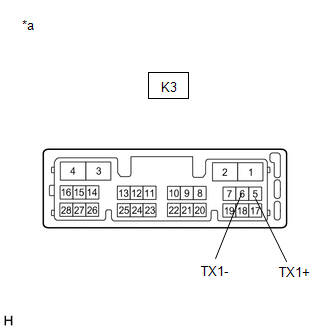
(a) Disconnect the K3 radio and display receiver assembly connector.
(b) Disconnect the K10 stereo component amplifier assembly connector.
(c) Measure the resistance according to the value(s) in the table below.
Standard Resistance:
|
Tester Connection | Condition |
Specified Condition |
|---|---|---|
|
K10-8 (TX+) - K3-5 (TX1+) |
Always | Below 1 Ω |
|
K10-7 (TX-) - K3-6 (TX1-) |
Always | Below 1 Ω |
|
K10-8 (TX+) or K3-5 (TX1+) - Body ground |
Always | 10 kΩ or higher |
|
K10-7 (TX-) or K3-6 (TX1-) - Body ground |
Always | 10 kΩ or higher |
| NG | | REPAIR OR REPLACE HARNESS OR CONNECTOR |
|
| 3. |
INSPECT MALFUNCTIONING PARTS |
(a) Disconnect and reconnect each slave unit one by one until the master unit returns to normal.
HINT:
- Check all slave units.
- If disconnecting a slave unit causes the master unit to return to normal, the slave unit is defective and should be replaced.
OK:
Master unit returns to normal.
| OK | | REPLACE MALFUNCTIONING PARTS |
| NG | | REPLACE RADIO AND DISPLAY RECEIVER ASSEMBLY
|
READ NEXT:
 Vehicle Speed Signal Circuit between Stereo Component Amplifier and Combination Meter
DESCRIPTION The stereo component amplifier assembly receives a vehicle speed signal from the combination meter assembly to control the ASL function.
HINT:
A voltage of 12 V or 5 V is output from
Reverse Signal Circuit
DESCRIPTION The radio and display receiver assembly receives a reverse signal from the BKUP LP relay. WIRING DIAGRAM
PROCEDURE
1.
CHECK BACK-UP LIGHT (a) Move the shift lever to R and
Voice Guidance Circuit between Radio Receiver and Stereo Component Amplifier
DESCRIPTION Using this circuit, the radio and display receiver assembly sends signals to the stereo component amplifier assembly. WIRING DIAGRAM
PROCEDURE
1.
CHECK HARNESS AND CONNECTOR
SEE MORE:
Problem Symptoms Table
PROBLEM SYMPTOMS TABLE If DTCs are not output but the malfunction persists, use the following table to determine which circuits to inspect for each problem symptom.
HINT: Refer to each inspection procedure for related problem symptoms. Vehicle Stability Control System
Symptom Suspected Are
Installation
INSTALLATION CAUTION / NOTICE / HINT
NOTICE:
Immediately after installing the brake pads, the braking performance may be reduced. Always perform a road test in a safe place while paying attention to the surroundings.
After replacing the rear disc brake pads, the brake pedal may feel soft
