Toyota Camry (XV70): Voice Guidance Circuit between Radio Receiver and Stereo Component Amplifier
DESCRIPTION
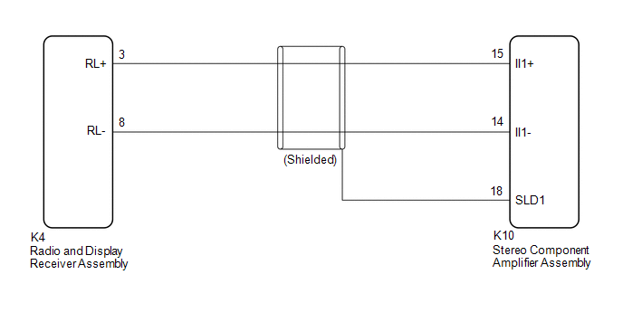
Using this circuit, the radio and display receiver assembly sends signals to the stereo component amplifier assembly.
WIRING DIAGRAM
PROCEDURE
| 1. |
CHECK HARNESS AND CONNECTOR (RADIO AND DISPLAY RECEIVER ASSEMBLY - STEREO COMPONENT AMPLIFIER ASSEMBLY) |
(a) Disconnect the K4 radio and display receiver assembly connector.
(b) Disconnect the K10 stereo component amplifier assembly connector.
(c) Measure the resistance according to the value(s) in the table below.
Standard Resistance:
|
Tester connection | Condition |
Specified condition |
|---|---|---|
|
K4-3 (RL+) - K10-15 (II1+) |
Always | Below 1 Ω |
|
K4-8 (RL-) - K10-14 (II1-) |
Always | Below 1 Ω |
|
K10-18 (SLD1) - Body ground |
Always | 10 kΩ or higher |
|
K4-3 (RL+) or K10-15 (II1+) - Body ground |
Always | 10 kΩ or higher |
|
K4-8 (RL-) or K10-14 (II1-) - Body ground |
Always | 10 kΩ or higher |
| OK | .gif) | PROCEED TO NEXT SUSPECTED AREA SHOWN IN PROBLEM SYMPTOMS TABLE
|
.gif)
| NG | | REPAIR OR REPLACE HARNESS OR CONNECTOR |
READ NEXT:
 Microphone Circuit between Microphone and Radio Receiver
DESCRIPTION
w/o Manual (SOS) Switch:
The radio and display receiver assembly, roof console box sub-assembly and telephone microphone assembly are connected to each other using the microphone co
Radio Receiver Power Source Circuit
DESCRIPTION This is the power source circuit to operate the radio and display receiver assembly. WIRING DIAGRAM
CAUTION / NOTICE / HINT
NOTICE: Inspect the fuses for circuits related to this syst
SEE MORE:
Idle Control System (P050500)
DESCRIPTION The idle speed is controlled by the ETCS (Electronic Throttle Control System). The ETCS is comprised of: 1) the one valve type throttle body; 2) the throttle actuator, which operates the throttle valve; 3) the throttle position sensor, which detects the opening angle of the throttle valv
Data List / Active Test
DATA LIST / ACTIVE TEST DATA LIST NOTICE:
In the table below, the values listed under "Normal Condition" are reference values. Do not depend solely on these reference values when deciding whether a part is faulty or not.
HINT: Using the Techstream to read the Data List allows the values or state
