Toyota Camry (XV70): Microphone Circuit between Microphone and Radio Receiver
DESCRIPTION
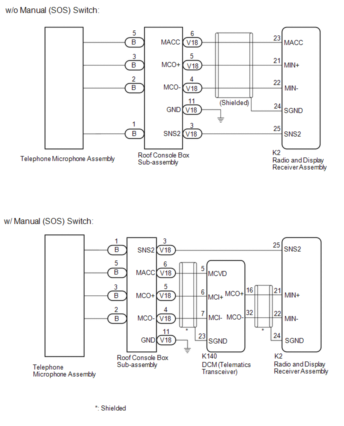
- w/o Manual (SOS) Switch:
The radio and display receiver assembly, roof console box sub-assembly and telephone microphone assembly are connected to each other using the microphone connection detection signal lines.
Using this circuit, the radio and display receiver assembly sends power to the roof console box sub-assembly and telephone microphone assembly, and the roof console box sub-assembly and telephone microphone assembly sends microphone signals to the radio and display receiver assembly.
- w/ Manual (SOS) Switch:
The radio and display receiver assembly, roof console box sub-assembly and telephone microphone assembly are connected to each other using the microphone connection detection signal lines.
Using this circuit, the DCM (telematics transceiver) sends power to the roof console box sub-assembly and telephone microphone assembly, and the roof console box sub-assembly and telephone microphone assembly sends microphone signals to the radio and display receiver assembly via the DCM (telematics transceiver).
WIRING DIAGRAM
w/ Sliding Roof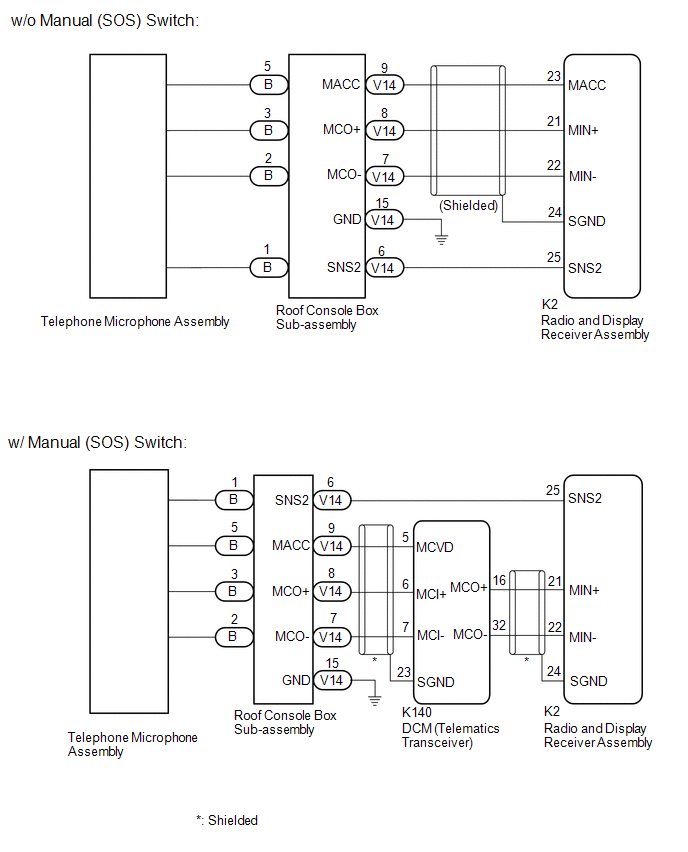 w/o Sliding Roof
CAUTION / NOTICE / HINT
NOTICE:
- Depending on the parts that are replaced during vehicle inspection or maintenance, performing initialization, registration or calibration may be needed. Refer to Precaution for Audio and Visual System.
Click here
.gif)
- When replacing the radio and display receiver assembly, always replace it with a new one. If a radio and display receiver assembly which was installed to another vehicle is used, the following may occur:
- A communication malfunction DTC may be stored.
- The radio and display receiver assembly may not operate normally.
- Before replacing the DCM (telematics transceiver), refer to Registration.
Click here
PROCEDURE
|
1. | CHECK MODEL |
(a) Choose the model to be inspected.
|
Result | Proceed to |
|---|---|
|
w/ Sliding Roof | A |
|
w/o Sliding Roof | B |
| B |
.gif) | GO TO STEP 19 |
|
.gif)
| 2. |
CHECK MICROPHONE (OPERATION CHECK) |
| (a) Enter the "Microphone Check" screen. Refer to Check Microphone in Operation Check. Click here |
|
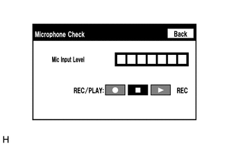
(b) When a voice is input into the microphone, check that the microphone input level meter changes according to the input voice.
OK:
Check result is normal.
|
Result | Proceed to |
|---|---|
|
NG (w/o Manual (SOS) Switch) |
A |
| NG (w/ Manual (SOS) Switch) |
B |
| OK |
C |
| B |
| GO TO STEP 9 |
| C |
| REPLACE RADIO AND DISPLAY RECEIVER ASSEMBLY
|
|
| 3. |
CHECK HARNESS AND CONNECTOR (RADIO AND DISPLAY RECEIVER ASSEMBLY - ROOF CONSOLE BOX SUB-ASSEMBLY) |
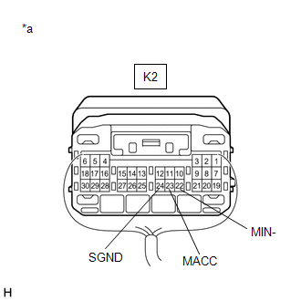
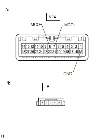
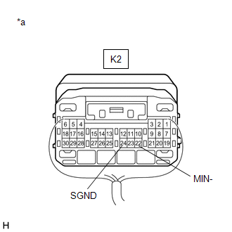
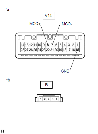
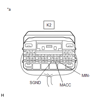
(a) Disconnect the K2 radio and display receiver assembly connector.
(b) Disconnect the V14 roof console box sub-assembly connector.
(c) Measure the resistance according to the value(s) in the table below.
Standard Resistance:
|
Tester Connection | Condition |
Specified Condition |
|---|---|---|
|
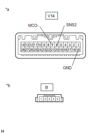
K2-25 (SNS2) - V14-6 (SNS2) |
Always | Below 1 Ω |
|
K2-23 (MACC) - V14-9 (MACC) |
Always | Below 1 Ω |
|
K2-21 (MIN+) - V14-8 (MCO+) |
Always | Below 1 Ω |
|
K2-22 (MIN-) - V14-7 (MCO-) |
Always | Below 1 Ω |
|
K2-25 (SNS2) or V14-6 (SNS2) - Body ground |
Always | 10 kΩ or higher |
|
K2-23 (MACC) or V14-9 (MACC) - Body ground |
Always | 10 kΩ or higher |
|
K2-21 (MIN+) or V14-8 (MCO+) - Body ground |
Always | 10 kΩ or higher |
|
K2-22 (MIN-) or V14-7 (MCO-) - Body ground |
Always | 10 kΩ or higher |
|
K2-24 (SGND) - Body ground |
Always | 10 kΩ or higher |
| NG | | REPAIR OR REPLACE HARNESS OR CONNECTOR |
|
| 4. |
INSPECT RADIO AND DISPLAY RECEIVER ASSEMBLY |
(a) Connect the K2 radio and display receiver assembly connector.
(b) Connect the V14 roof console box sub-assembly connector.
| (c) Measure the voltage according to the value(s) in the table below. Standard Voltage:
|
|
(d) Measure the resistance according to the value(s) in the table below.
Standard Resistance:
|
Tester Connection | Condition |
Specified Condition |
|---|---|---|
|
K2-24 (SGND) - Body ground |
Always | Below 1 Ω |
|
K2-22 (MIN-) - Body ground |
Always | Below 1 Ω |
| NG | | REPLACE RADIO AND DISPLAY RECEIVER ASSEMBLY
|
|
| 5. |
INSPECT ROOF CONSOLE BOX SUB-ASSEMBLY |
(a) Remove the roof console box sub-assembly.
Click here
(b) Connect the B telephone microphone assembly connector.
| (c) Measure the resistance according to the value(s) in the table below. Standard Resistance:
|
|
.png)
| NG | | GO TO STEP 8 |
|
| 6. |
INSPECT ROOF CONSOLE BOX SUB-ASSEMBLY (OUTPUT TO RADIO AND DISPLAY RECEIVER ASSEMBLY) |
(a) Connect the K2 radio and display receiver assembly connector.
(b) Connect the V14 roof console box sub-assembly connector.
(c) Turn the ignition switch to ACC.
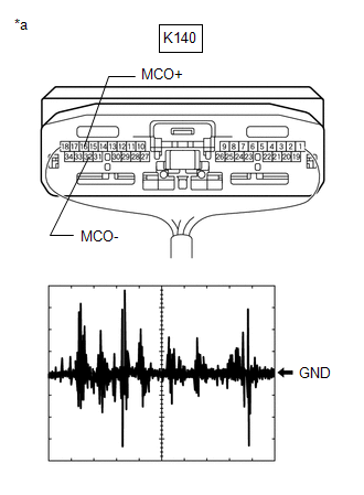
| (d) Connect an oscilloscope to terminals 8 (MCO+) and 7 (MCO-) of the V14 roof console box sub-assembly connector. |
|
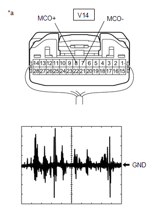
(e) Check the signal waveform according to the condition(s) in the table below.
|
Item | Condition |
|---|---|
|
Measurement terminal |
V14-8 (MCO+) - V14-7 (MCO-) |
|
Tool setting | 50 mV/DIV., 500 ms/DIV. |
|
Vehicle condition |
|
OK:
The waveform is similar to that shown in the illustration.
HINT:
The oscilloscope waveform shown in the illustration is an example for reference only.
| OK | | PROCEED TO NEXT SUSPECTED AREA SHOWN IN PROBLEM SYMPTOMS TABLE
|
|
| 7. |
INSPECT ROOF CONSOLE BOX SUB-ASSEMBLY |
(a) Remove the roof console box sub-assembly.
Click here
(b) Disconnect the B telephone microphone assembly connector.
| (c) Measure the resistance according to the value(s) in the table below. Standard Resistance:
|
|
| OK | | REPLACE TELEPHONE MICROPHONE ASSEMBLY |
| NG | | REPLACE ROOF CONSOLE BOX SUB-ASSEMBLY |
| 8. |
INSPECT ROOF CONSOLE BOX SUB-ASSEMBLY |
(a) Remove the roof console box sub-assembly.
Click here
(b) Disconnect the B telephone microphone assembly connector.
| (c) Measure the resistance according to the value(s) in the table below. Standard Resistance:
|
|

| OK | | REPLACE TELEPHONE MICROPHONE ASSEMBLY |
| NG | | REPLACE ROOF CONSOLE BOX SUB-ASSEMBLY |
| 9. |
CHECK HARNESS AND CONNECTOR (RADIO AND DISPLAY RECEIVER ASSEMBLY - ROOF CONSOLE BOX SUB-ASSEMBLY) |
(a) Disconnect the K2 radio and display receiver assembly connector.
(b) Disconnect the V14 roof console box sub-assembly connector.
(c) Measure the resistance according to the value(s) in the table below.
Standard Resistance:
|
Tester Connection | Condition |
Specified Condition |
|---|---|---|
|
K2-25 (SNS2) - V14-6 (SNS2) |
Always | Below 1 Ω |
|
K2-25 (SNS2) or V14-6 (SNS2) - Body ground |
Always | 10 kΩ or higher |
| NG | | REPAIR OR REPLACE HARNESS OR CONNECTOR |
|
| 10. |
CHECK HARNESS AND CONNECTOR (RADIO AND DISPLAY RECEIVER ASSEMBLY - DCM (TELEMATICS TRANSCEIVER)) |
(a) Disconnect the K2 radio and display receiver assembly connector.
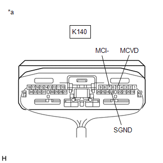
(b) Disconnect the K140 DCM (telematics transceiver) connector.
(c) Measure the resistance according to the value(s) in the table below.
Standard Resistance:
|
Tester Connection | Condition |
Specified Condition |
|---|---|---|
|
K2-21 (MIN+) - K140-16 (MCO+) |
Always | Below 1 Ω |
|
K2-22 (MIN-) - K140-32 (MCO-) |
Always | Below 1 Ω |
|
K2-21 (MIN+) or K140-16 (MCO+) - Body ground |
Always | 10 kΩ or higher |
|
K2-22 (MIN-) or K140-32 (MCO-) - Body ground |
Always | 10 kΩ or higher |
|
K2-24 (SGND) - Body ground |
Always | 10 kΩ or higher |
| NG | | REPAIR OR REPLACE HARNESS OR CONNECTOR |
|
| 11. |
CHECK HARNESS AND CONNECTOR (DCM (TELEMATICS TRANSCEIVER) - ROOF CONSOLE BOX SUB-ASSEMBLY) |
(a) Disconnect the K140 DCM (telematics transceiver) connector.
(b) Disconnect the V14 roof console box sub-assembly connector.
(c) Measure the resistance according to the value(s) in the table below.
Standard Resistance:
|
Tester Connection | Condition |
Specified Condition |
|---|---|---|
|
K140-5 (MCVD) - V14-9 (MACC) |
Always | Below 1 Ω |
|
K140-6 (MCI+) - V14-8 (MCO+) |
Always | Below 1 Ω |
|
K140-7 (MCI-) - V14-7 (MCO-) |
Always | Below 1 Ω |
|
K140-5 (MCVD) or V14-9 (MACC) - Body ground |
Always | 10 kΩ or higher |
|
K140-6 (MCI+) or V14-8 (MCO+) - Body ground |
Always | 10 kΩ or higher |
|
K140-7 (MCI-) or V14-7 (MCO-) - Body ground |
Always | 10 kΩ or higher |
|
K140-23 (SGND) - Body ground |
Always | 10 kΩ or higher |
| NG | | REPAIR OR REPLACE HARNESS OR CONNECTOR |
|
| 12. |
INSPECT RADIO AND DISPLAY RECEIVER ASSEMBLY |
(a) Disconnect the K140 DCM (telematics transceiver) connector.
| (b) Connect the K2 radio and display receiver assembly connector. |
|
(c) Measure the resistance according to the value(s) in the table below.
Standard Resistance:
|
Tester Connection | Condition |
Specified Condition |
|---|---|---|
|
K2-24 (SGND) - Body ground |
Always | Below 1 Ω |
|
K2-22 (MIN-) - Body ground |
Always | Below 1 Ω |
| NG | | REPLACE RADIO AND DISPLAY RECEIVER ASSEMBLY
|
|
| 13. |
INSPECT DCM (TELEMATICS TRANSCEIVER) |
(a) Connect the K140 DCM (telematics transceiver) connector.
| (b) Measure the voltage according to the value(s) in the table below. Standard Voltage:
|
|
(c) Measure the resistance according to the value(s) in the table below.
Standard Resistance:
|
Tester Connection | Condition |
Specified Condition |
|---|---|---|
|
K140-7 (MCI-) - Body ground |
Always | Below 1 Ω |
|
K140-23 (SGND) - Body ground |
Always | Below 1 Ω |
| NG | | REPLACE DCM (TELEMATICS TRANSCEIVER)
|
|
| 14. |
INSPECT ROOF CONSOLE BOX SUB-ASSEMBLY |
(a) Remove the roof console box sub-assembly.
Click here
(b) Connect the B telephone microphone assembly connector.
| (c) Measure the resistance according to the value(s) in the table below. Standard Resistance:
|
|
| NG | | GO TO STEP 18 |
|
| 15. |
INSPECT ROOF CONSOLE BOX SUB-ASSEMBLY (OUTPUT TO DCM (TELEMATICS TRANSCEIVER)) |
(a) Connect the K2 radio and display receiver assembly connector.
(b) Connect the V14 roof console box sub-assembly connector.
(c) Connect the K140 DCM (telematics transceiver) connector.
(d) Turn the ignition switch to ACC.
| (e) Connect an oscilloscope to terminals 8 (MCO+) and 7 (MCO-) of the V14 roof console box sub-assembly connector. |
|
(f) Check the signal waveform according to the condition(s) in the table below.
|
Item | Condition |
|---|---|
|
Measurement terminal |
V14-8 (MCO+) - V14-7 (MCO-) |
|
Tool setting | 50 mV/DIV., 500 ms/DIV. |
|
Vehicle condition |
|
OK:
The waveform is similar to that shown in the illustration.
HINT:
The oscilloscope waveform shown in the illustration is an example for reference only.
| NG | | GO TO STEP 17 |
|
| 16. |
INSPECT DCM (TELEMATICS TRANSCEIVER) (OUTPUT TO RADIO AND DISPLAY RECEIVER ASSEMBLY) |
(a) Connect the K2 radio and display receiver assembly connector.
(b) Connect the V14 roof console box sub-assembly connector.
(c) Connect the K140 DCM (telematics transceiver) connector.
(d) Turn the ignition switch to ACC.
| (e) Connect an oscilloscope to terminals 16 (MCO+) and 32 (MCO-) of the K140 DCM (telematics transceiver) connector. |
|
(f) Check the signal waveform according to the condition(s) in the table below.
|
Item | Condition |
|---|---|
|
Measurement terminal |
K140-16 (MCO+) - K140-32 (MCO-) |
|
Tool setting | 50 mV/DIV., 500 ms/DIV. |
|
Vehicle condition |
|
OK:
The waveform is similar to that shown in the illustration.
HINT:
The oscilloscope waveform shown in the illustration is an example for reference only.
| OK | | PROCEED TO NEXT SUSPECTED AREA SHOWN IN PROBLEM SYMPTOMS TABLE
|
| NG | | REPLACE DCM (TELEMATICS TRANSCEIVER)
|
| 17. |
INSPECT ROOF CONSOLE BOX SUB-ASSEMBLY |
(a) Remove the roof console box sub-assembly.
Click here
(b) Disconnect the B telephone microphone assembly connector.
| (c) Measure the resistance according to the value(s) in the table below. Standard Resistance:
|
|
| OK | | REPLACE TELEPHONE MICROPHONE ASSEMBLY |
| NG | | REPLACE ROOF CONSOLE BOX SUB-ASSEMBLY |
| 18. |
INSPECT ROOF CONSOLE BOX SUB-ASSEMBLY |
(a) Remove the roof console box sub-assembly.
Click here
(b) Disconnect the B telephone microphone assembly connector.
| (c) Measure the resistance according to the value(s) in the table below. Standard Resistance:
|
|
| OK | | REPLACE TELEPHONE MICROPHONE ASSEMBLY |
| NG | | REPLACE ROOF CONSOLE BOX SUB-ASSEMBLY |
| 19. |
CHECK MICROPHONE (OPERATION CHECK) |
| (a) Enter the "Microphone Check" screen. Refer to Check Microphone in Operation Check. Click here |
|
(b) When a voice is input into the microphone, check that the microphone input level meter changes according to the input voice.
OK:
Check result is normal.
|
Result | Proceed to |
|---|---|
|
NG (w/o Manual (SOS) Switch) |
A |
| NG (w/ Manual (SOS) Switch) |
B |
| OK |
C |
| B |
| GO TO STEP 26 |
| C |
| REPLACE RADIO AND DISPLAY RECEIVER ASSEMBLY
|
|
| 20. |
CHECK HARNESS AND CONNECTOR (RADIO AND DISPLAY RECEIVER ASSEMBLY - ROOF CONSOLE BOX SUB-ASSEMBLY) |
(a) Disconnect the K2 radio and display receiver assembly connector.
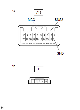
(b) Disconnect the V18 roof console box sub-assembly connector.
(c) Measure the resistance according to the value(s) in the table below.
Standard Resistance:
|
Tester Connection | Condition |
Specified Condition |
|---|---|---|
|
K2-25 (SNS2) - V18-3 (SNS2) |
Always | Below 1 Ω |
|
K2-23 (MACC) - V18-6 (MACC) |
Always | Below 1 Ω |
|
K2-21 (MIN+) - V18-5 (MCO+) |
Always | Below 1 Ω |
|
K2-22 (MIN-) - V18-4 (MCO-) |
Always | Below 1 Ω |
|
K2-25 (SNS2) or V18-3 (SNS2) - Body ground |
Always | 10 kΩ or higher |
|
K2-23 (MACC) or V18-6 (MACC) - Body ground |
Always | 10 kΩ or higher |
|
K2-21 (MIN+) or V18-5 (MCO+) - Body ground |
Always | 10 kΩ or higher |
|
K2-22 (MIN-) or V18-4 (MCO-) - Body ground |
Always | 10 kΩ or higher |
|
K2-24 (SGND) - Body ground |
Always | 10 kΩ or higher |
| NG | | REPAIR OR REPLACE HARNESS OR CONNECTOR |
|
| 21. |
INSPECT RADIO AND DISPLAY RECEIVER ASSEMBLY |
(a) Connect the K2 radio and display receiver assembly connector.
(b) Connect the V18 roof console box sub-assembly connector.
| (c) Measure the voltage according to the value(s) in the table below. Standard Voltage:
|
|
(d) Measure the resistance according to the value(s) in the table below.
Standard Resistance:
|
Tester Connection | Condition |
Specified Condition |
|---|---|---|
|
K2-24 (SGND) - Body ground |
Always | Below 1 Ω |
|
K2-22 (MIN-) - Body ground |
Always | Below 1 Ω |
| NG | | REPLACE RADIO AND DISPLAY RECEIVER ASSEMBLY
|
|
| 22. |
INSPECT ROOF CONSOLE BOX SUB-ASSEMBLY |
(a) Remove the roof console box sub-assembly.
Click here
(b) Connect the B telephone microphone assembly connector.
| (c) Measure the resistance according to the value(s) in the table below. Standard Resistance:
|
|
.png)
| NG | | GO TO STEP 25 |
|
| 23. |
INSPECT ROOF CONSOLE BOX SUB-ASSEMBLY (OUTPUT TO RADIO AND DISPLAY RECEIVER ASSEMBLY) |
(a) Connect the K2 radio and display receiver assembly connector.
(b) Connect the V18 roof console box sub-assembly connector.
(c) Turn the ignition switch to ACC.
| (d) Connect an oscilloscope to terminals 5 (MCO+) and 4 (MCO-) of the V18 roof console box sub-assembly connector. |
|
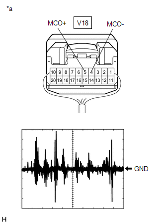
(e) Check the signal waveform according to the condition(s) in the table below.
|
Item | Condition |
|---|---|
|
Measurement terminal |
V18-5 (MCO+) - V18-4 (MCO-) |
|
Tool setting | 50 mV/DIV., 500 ms/DIV. |
|
Vehicle condition |
|
OK:
The waveform is similar to that shown in the illustration.
HINT:
The oscilloscope waveform shown in the illustration is an example for reference only.
| OK | | PROCEED TO NEXT SUSPECTED AREA SHOWN IN PROBLEM SYMPTOMS TABLE
|
|
| 24. |
INSPECT ROOF CONSOLE BOX SUB-ASSEMBLY |
(a) Remove the roof console box sub-assembly.
Click here
(b) Disconnect the B telephone microphone assembly connector.
| (c) Measure the resistance according to the value(s) in the table below. Standard Resistance:
|
|
| OK | | REPLACE TELEPHONE MICROPHONE ASSEMBLY |
| NG | | REPLACE ROOF CONSOLE BOX SUB-ASSEMBLY |
| 25. |
INSPECT ROOF CONSOLE BOX SUB-ASSEMBLY |
(a) Remove the roof console box sub-assembly.
Click here
(b) Disconnect the B telephone microphone assembly connector.
| (c) Measure the resistance according to the value(s) in the table below. Standard Resistance:
|
|
| OK | | REPLACE TELEPHONE MICROPHONE ASSEMBLY |
| NG | | REPLACE ROOF CONSOLE BOX SUB-ASSEMBLY |
| 26. |
CHECK HARNESS AND CONNECTOR (RADIO AND DISPLAY RECEIVER ASSEMBLY - ROOF CONSOLE BOX SUB-ASSEMBLY) |
(a) Disconnect the K2 radio and display receiver assembly connector.
(b) Disconnect the V18 roof console box sub-assembly connector.
(c) Measure the resistance according to the value(s) in the table below.
Standard Resistance:
|
Tester Connection | Condition |
Specified Condition |
|---|---|---|
|
K2-25 (SNS2) - V18-3 (SNS2) |
Always | Below 1 Ω |
|
K2-25 (SNS2) or V18-3 (SNS2) - Body ground |
Always | 10 kΩ or higher |
| NG | | REPAIR OR REPLACE HARNESS OR CONNECTOR |
|
| 27. |
CHECK HARNESS AND CONNECTOR (RADIO AND DISPLAY RECEIVER ASSEMBLY - DCM (TELEMATICS TRANSCEIVER)) |
(a) Disconnect the K2 radio and display receiver assembly connector.
(b) Disconnect the K140 DCM (telematics transceiver) connector.
(c) Measure the resistance according to the value(s) in the table below.
Standard Resistance:
|
Tester Connection | Condition |
Specified Condition |
|---|---|---|
|
K2-21 (MIN+) - K140-16 (MCO+) |
Always | Below 1 Ω |
|
K2-22 (MIN-) - K140-32 (MCO-) |
Always | Below 1 Ω |
|
K2-21 (MIN+) or K140-16 (MCO+) - Body ground |
Always | 10 kΩ or higher |
|
K2-22 (MIN-) or K140-32 (MCO-) - Body ground |
Always | 10 kΩ or higher |
|
K2-24 (SGND) - Body ground |
Always | 10 kΩ or higher |
| NG | | REPAIR OR REPLACE HARNESS OR CONNECTOR |
|
| 28. |
CHECK HARNESS AND CONNECTOR (DCM (TELEMATICS TRANSCEIVER) - ROOF CONSOLE BOX SUB-ASSEMBLY) |
(a) Disconnect the K140 DCM (telematics transceiver) connector.
(b) Disconnect the V18 roof console box sub-assembly connector.
(c) Measure the resistance according to the value(s) in the table below.
Standard Resistance:
|
Tester Connection | Condition |
Specified Condition |
|---|---|---|
|
K140-5 (MCVD) - V18-6 (MACC) |
Always | Below 1 Ω |
|
K140-6 (MCI+) - V18-5 (MCO+) |
Always | Below 1 Ω |
|
K140-7 (MCI-) - V18-4 (MCO-) |
Always | Below 1 Ω |
|
K140-5 (MCVD) or V18-6 (MACC) - Body ground |
Always | 10 kΩ or higher |
|
K140-6 (MCI+) or V18-5 (MCO+) - Body ground |
Always | 10 kΩ or higher |
|
K140-7 (MCI-) or V18-4 (MCO-) - Body ground |
Always | 10 kΩ or higher |
|
K140-23 (SGND) - Body ground |
Always | 10 kΩ or higher |
| NG | | REPAIR OR REPLACE HARNESS OR CONNECTOR |
|
| 29. |
INSPECT RADIO AND DISPLAY RECEIVER ASSEMBLY |
(a) Disconnect the K140 DCM (telematics transceiver) connector.
| (b) Connect the K2 radio and display receiver assembly connector. |
|
(c) Measure the resistance according to the value(s) in the table below.
Standard Resistance:
|
Tester Connection | Condition |
Specified Condition |
|---|---|---|
|
K2-24 (SGND) - Body ground |
Always | Below 1 Ω |
|
K2-22 (MIN-) - Body ground |
Always | Below 1 Ω |
| NG | | REPLACE RADIO AND DISPLAY RECEIVER ASSEMBLY
|
|
| 30. |
INSPECT DCM (TELEMATICS TRANSCEIVER) |
(a) Connect the K140 DCM (telematics transceiver) connector.
| (b) Measure the voltage according to the value(s) in the table below. Standard Voltage:
|
|
(c) Measure the resistance according to the value(s) in the table below.
Standard Resistance:
|
Tester Connection | Condition |
Specified Condition |
|---|---|---|
|
K140-7 (MCI-) - Body ground |
Always | Below 1 Ω |
|
K140-23 (SGND) - Body ground |
Always | Below 1 Ω |
| NG | | REPLACE DCM (TELEMATICS TRANSCEIVER)
|
|
| 31. |
INSPECT ROOF CONSOLE BOX SUB-ASSEMBLY |
(a) Remove the roof console box sub-assembly.
Click here
(b) Connect the B telephone microphone assembly connector.
| (c) Measure the resistance according to the value(s) in the table below. Standard Resistance:
|
|
| NG | | GO TO STEP 35 |
|
| 32. |
INSPECT ROOF CONSOLE BOX SUB-ASSEMBLY (OUTPUT TO RADIO AND DISPLAY RECEIVER ASSEMBLY) |
(a) Connect the K2 radio and display receiver assembly connector.
(b) Connect the V18 roof console box sub-assembly connector.
(c) Turn the ignition switch to ACC.
| (d) Connect an oscilloscope to terminals 5 (MCO+) and 4 (MCO-) of the V18 roof console box sub-assembly connector. |
|
(e) Check the signal waveform according to the condition(s) in the table below.
|
Item | Condition |
|---|---|
|
Measurement terminal |
V18-5 (MCO+) - V18-4 (MCO-) |
|
Tool setting | 50 mV/DIV., 500 ms/DIV. |
|
Vehicle condition |
|
OK:
The waveform is similar to that shown in the illustration.
HINT:
The oscilloscope waveform shown in the illustration is an example for reference only.
| NG | | GO TO STEP 34 |
|
| 33. |
INSPECT DCM (TELEMATICS TRANSCEIVER) (OUTPUT TO RADIO AND DISPLAY RECEIVER ASSEMBLY) |
(a) Connect the K2 radio and display receiver assembly connector.
(b) Connect the V18 roof console box sub-assembly connector.
(c) Connect the K140 DCM (telematics transceiver) connector.
(d) Turn the ignition switch to ACC.
| (e) Connect an oscilloscope to terminals 16 (MCO+) and 32 (MCO-) of the K140 DCM (telematics transceiver) connector. |
|
(f) Check the signal waveform according to the condition(s) in the table below.
|
Item | Condition |
|---|---|
|
Measurement terminal |
K140-16 (MCO+) - K140-32 (MCO-) |
|
Tool setting | 50 mV/DIV., 500 ms/DIV. |
|
Vehicle condition |
|
OK:
The waveform is similar to that shown in the illustration.
HINT:
The oscilloscope waveform shown in the illustration is an example for reference only.
| OK | | PROCEED TO NEXT SUSPECTED AREA SHOWN IN PROBLEM SYMPTOMS TABLE
|
| NG | | REPLACE DCM (TELEMATICS TRANSCEIVER)
|
| 34. |
INSPECT ROOF CONSOLE BOX SUB-ASSEMBLY |
(a) Remove the roof console box sub-assembly.
Click here
(b) Disconnect the B telephone microphone assembly connector.
| (c) Measure the resistance according to the value(s) in the table below. Standard Resistance:
|
|
| OK | | REPLACE TELEPHONE MICROPHONE ASSEMBLY |
| NG | | REPLACE ROOF CONSOLE BOX SUB-ASSEMBLY |
| 35. |
INSPECT ROOF CONSOLE BOX SUB-ASSEMBLY |
(a) Remove the roof console box sub-assembly.
Click here
(b) Disconnect the B telephone microphone assembly connector.
| (c) Measure the resistance according to the value(s) in the table below. Standard Resistance:
|
|
| OK | | REPLACE TELEPHONE MICROPHONE ASSEMBLY |
| NG | | REPLACE ROOF CONSOLE BOX SUB-ASSEMBLY |
READ NEXT:
 Radio Receiver Power Source Circuit
DESCRIPTION This is the power source circuit to operate the radio and display receiver assembly. WIRING DIAGRAM
CAUTION / NOTICE / HINT
NOTICE: Inspect the fuses for circuits related to this syst
Components
COMPONENTS ILLUSTRATION
*A for Front Passenger Side
*B for Driver Side
*C w/o Courtesy Light
*D w/ Courtesy Light
*1 COURTESY LIGHT ASSEMBLY
*2
SEE MORE:
Throttle / Pedal Position Sensor / Switch "A" Circuit Voltage Out of Range (P01201C)
DESCRIPTION Refer to DTC P012011. Click here
DTC No. Detection Item
DTC Detection Condition Trouble Area
MIL Memory
Note P01201C
Throttle / Pedal Position Sensor / Switch "A" Circuit Voltage Out of Range
The difference between the output voltage of VTA1
Right Rear Wheel Speed Sensor Circuit Intermittent (C05121F)
DESCRIPTION Refer to DTC C051212 Click here
DTC No. Detection Item
DTC Detection Condition Trouble Area
C05121F Right Rear Wheel Speed Sensor Circuit Intermittent
The speed sensor signal is excessively noisy.
The calculated change in wheel speed is more
