Toyota Camry (XV70): Vehicle Speed Signal Circuit between Stereo Component Amplifier and Combination Meter
DESCRIPTION
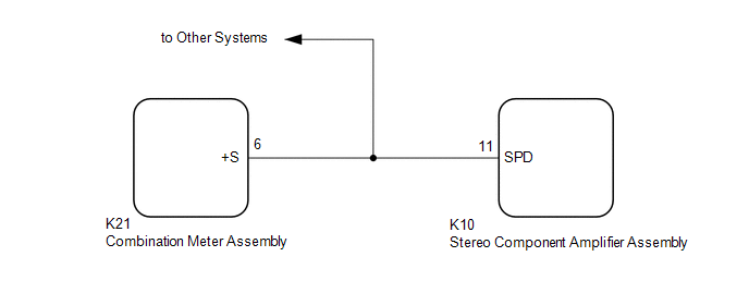
The stereo component amplifier assembly receives a vehicle speed signal from the combination meter assembly to control the ASL function.
HINT:
- A voltage of 12 V or 5 V is output from each ECU and then input to the combination meter assembly. The signal is changed to a pulse signal at the transistor in the combination meter assembly. Each ECU controls its respective systems based on this pulse signal.
- If a short occurs in any of the ECUs or in the wire harness connected to an ECU, all systems in the following diagram will not operate normally.
WIRING DIAGRAM
PROCEDURE
| 1. |
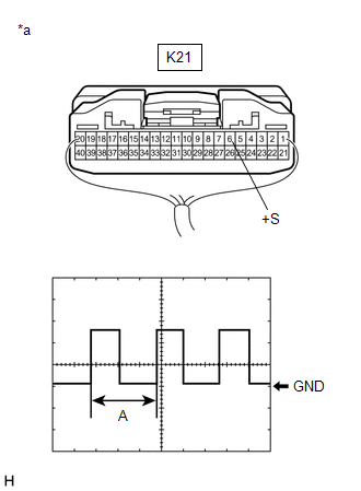
INSPECT COMBINATION METER ASSEMBLY (OUTPUT WAVEFORM) |
| (a) Check the output waveform. (1) Remove the combination meter assembly with the connector(s) still connected. (2) Connect an oscilloscope to terminal K21-6 (+S) and body ground. (3) Turn the ignition switch to ON. (4) Turn a wheel slowly. (5) Check the signal waveform according to the condition(s) in the table below.
OK: The waveform is similar to that shown in the illustration. HINT: When the system is functioning normally, one wheel revolution generates 4 pulses. As the vehicle speed increases, the width indicated by (A) in the illustration narrows. |
|
| NG | .gif) | GO TO METER / GAUGE SYSTEM |
|
.gif)
| 2. |
INSPECT STEREO COMPONENT AMPLIFIER ASSEMBLY (INPUT WAVEFORM) |
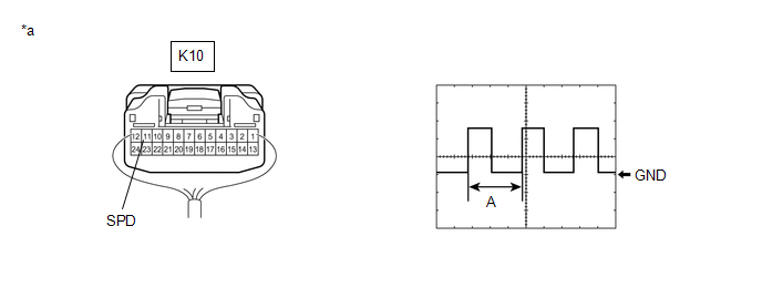
(a) Check the input waveform.
|
*a | Component with harness connected (Stereo Component Amplifier Assembly) |
- | - |
(1) Remove the stereo component amplifier assembly with the connector(s) still connected.
(2) Connect an oscilloscope to terminal K10-11 (SPD) and body ground.
(3) Turn the ignition switch to ON.
(4) Turn a wheel slowly.
(5) Check the signal waveform according to the condition(s) in the table below.
|
Item | Condition |
|---|---|
|
Measurement terminal |
K10-11 (SPD) - Body ground |
|
Tool setting | 5 V/DIV., 20 ms./DIV. |
|
Vehicle condition | Wheel being rotated |
OK:
The waveform is similar to that shown in the illustration.
HINT:
When the system is functioning normally, one wheel revolution generates 4 pulses. As the vehicle speed increases, the width indicated by (A) in the illustration narrows.
| OK | | PROCEED TO NEXT SUSPECTED AREA SHOWN IN PROBLEM SYMPTOMS TABLE
|
.gif)
| NG | | REPAIR OR REPLACE HARNESS OR CONNECTOR |
READ NEXT:
 Reverse Signal Circuit
DESCRIPTION The radio and display receiver assembly receives a reverse signal from the BKUP LP relay. WIRING DIAGRAM
PROCEDURE
1.
CHECK BACK-UP LIGHT (a) Move the shift lever to R and
Voice Guidance Circuit between Radio Receiver and Stereo Component Amplifier
DESCRIPTION Using this circuit, the radio and display receiver assembly sends signals to the stereo component amplifier assembly. WIRING DIAGRAM
PROCEDURE
1.
CHECK HARNESS AND CONNECTOR
Microphone Circuit between Microphone and Radio Receiver
DESCRIPTION
w/o Manual (SOS) Switch:
The radio and display receiver assembly, roof console box sub-assembly and telephone microphone assembly are connected to each other using the microphone co
SEE MORE:
Components
COMPONENTS ILLUSTRATION
*1 BRAKE LINE
*2 BRAKE MASTER CYLINDER SUB-ASSEMBLY
Tightening torque for "Major areas involving basic vehicle performance such as moving/turning/stopping" : N*m (kgf*cm, ft.*lbf)
* For use with a union nut wrench ILLUSTRATION
Removal
REMOVAL CAUTION / NOTICE / HINT
HINT:
Use the same procedure for the RH side and LH side.
The following procedure is for the LH side.
The front speed sensor rotor is a component of the front axle hub sub-assembly. If the front speed sensor rotor is malfunctioning, replace the front axl
