Toyota Camry (XV70): Reverse Signal Circuit
DESCRIPTION
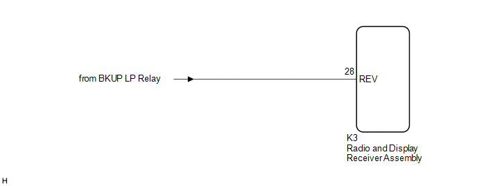
The radio and display receiver assembly receives a reverse signal from the BKUP LP relay.
WIRING DIAGRAM
PROCEDURE
| 1. |
CHECK BACK-UP LIGHT |
(a) Move the shift lever to R and check if the back-up lights come on.
OK:
The back-up lights come on.
| NG | .gif) | GO TO LIGHTING SYSTEM
|
.gif)
|
.gif)
| 2. |
CHECK HARNESS AND CONNECTOR (REVERSE SIGNAL) |
(a) Disconnect the K3 radio and display receiver assembly connector.
(b) Measure the voltage according to the value(s) in the table below.
Standard Voltage:
|
Tester Connection | Condition |
Specified Condition |
|---|---|---|
|
K3-28 (REV) - Body ground |
Ignition switch ON Shift lever in R |
11 to 14 V |
|
K3-28 (REV) - Body ground |
Ignition switch ON Shift lever not in R |
Below 1 V |
| OK | | PROCEED TO NEXT SUSPECTED AREA SHOWN IN PROBLEM SYMPTOMS TABLE
|
| NG | | REPAIR OR REPLACE HARNESS OR CONNECTOR |
READ NEXT:
 Voice Guidance Circuit between Radio Receiver and Stereo Component Amplifier
DESCRIPTION Using this circuit, the radio and display receiver assembly sends signals to the stereo component amplifier assembly. WIRING DIAGRAM
PROCEDURE
1.
CHECK HARNESS AND CONNECTOR
Microphone Circuit between Microphone and Radio Receiver
DESCRIPTION
w/o Manual (SOS) Switch:
The radio and display receiver assembly, roof console box sub-assembly and telephone microphone assembly are connected to each other using the microphone co
Radio Receiver Power Source Circuit
DESCRIPTION This is the power source circuit to operate the radio and display receiver assembly. WIRING DIAGRAM
CAUTION / NOTICE / HINT
NOTICE: Inspect the fuses for circuits related to this syst
SEE MORE:
On-vehicle Inspection
ON-VEHICLE INSPECTION PROCEDURE
1. CONNECT TECHSTREAM (a) Connect the Techstream to the DLC3 with the ignition switch off.
(b) Start the engine and run it at idle. (c) Turn the Techstream on.
(d) Enter the following menus: Chassis / Brake / Active Test. HINT:
Refer to the Techstream operator
Fuel Rail Pressure Sensor (Low) Circuit Short to Battery or Open (P107A15)
DESCRIPTION Refer to DTC P107A11. Click here
DTC No. Detection Item
DTC Detection Condition Trouble Area
MIL Memory
Note P107A15
Fuel Rail Pressure Sensor (Low) Circuit Short to Battery or Open
The fuel pressure sensor (for low pressure side) output vol
