Toyota Camry (XV70): Data Signal Circuit between Radio Receiver and Stereo Jack Adapter
DESCRIPTION
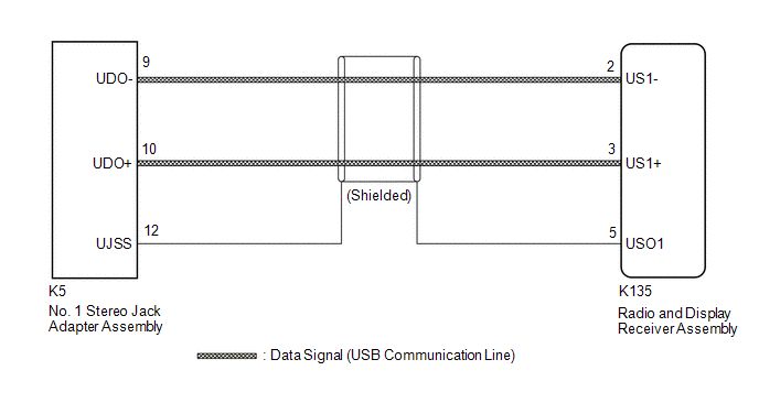
The No. 1 stereo jack adapter assembly sends the sound data signal or image data signal from a USB device to the radio and display receiver assembly via this circuit.
WIRING DIAGRAM
PROCEDURE
| 1. |
CHECK HARNESS AND CONNECTOR (RADIO AND DISPLAY RECEIVER ASSEMBLY - NO. 1 STEREO JACK ADAPTER ASSEMBLY) |
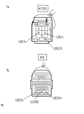
(a) Disconnect the K135 radio and display receiver assembly connector.
(b) Disconnect the K5 No. 1 stereo jack adapter assembly connector.
| (c) Measure the resistance according to the value(s) in the table below. Standard Resistance:
|
|
| OK | .gif) | PROCEED TO NEXT SUSPECTED AREA SHOWN IN PROBLEM SYMPTOMS TABLE
|
.gif)
| NG | | REPAIR OR REPLACE HARNESS OR CONNECTOR |
READ NEXT:
 Mute Signal Circuit between Radio Receiver and Stereo Component Amplifier
DESCRIPTION This circuit sends a signal to the stereo component amplifier assembly to mute noise. Because of that, the noise produced by changing the sound source ceases.
If there is an open in the
Mute Signal Circuit between Stereo Component Amplifier and Telematics Transceiver
DESCRIPTION The DCM (telematics transceiver) sends a mute signal to the stereo component amplifier assembly.
The stereo component amplifier assembly controls the volume according to the mute signal
Mute Signal Circuit between Radio Receiver and Telematics Transceiver
DESCRIPTION The DCM (telematics transceiver) sends a mute signal to the radio and display receiver assembly.
The radio and display receiver assembly controls the volume according to the mute signal
SEE MORE:
Precaution
PRECAUTION PRECAUTION FOR DISCONNECTING CABLE FROM NEGATIVE BATTERY TERMINAL
NOTICE: When disconnecting the cable from the negative (-) battery terminal, initialize the following system(s) after the cable is reconnected:
System Name See Procedure
Lane Tracing Assist System
Parts Location
PARTS LOCATION ILLUSTRATION
*1 ECM
*2 ENGINE ROOM RELAY BLOCK AND JUNCTION BLOCK ASSEMBLY
- ST RELAY - EFI-MAIN NO. 1 FUSE - J/B-B FUSE - ETCS FUSE ILLUSTRATION
*A w/ Shift Paddle Switch
- -
*1 SHIFT LOCK CONTROL UNIT ASSEMBLY
- TRANSMISSIO
