Toyota Camry (XV70): Speaker Circuit
DESCRIPTION
for 6 Speakers- If there is a short in a speaker circuit, the radio and display receiver assembly detects it and stops output to the speakers.
Thus sound cannot be heard from the speakers even if there is no malfunction in the radio and display receiver assembly, DCM (telematics transceiver)* or speakers.
- If there is a short in a speaker circuit, the stereo component amplifier assembly detects it and stops output to the speakers.
Thus sound cannot be heard from the speakers even if there is no malfunction in the stereo component amplifier assembly, DCM (telematics transceiver)* or speakers.
- *: w/ Manual (SOS) Switch
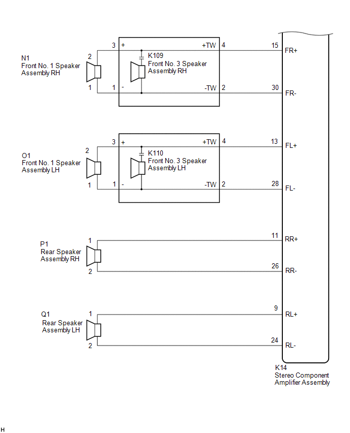
WIRING DIAGRAM
for 6 Speakers.png) for 9 Speakers
for 9 Speakers
.png)
CAUTION / NOTICE / HINT
NOTICE:
- Depending on the parts that are replaced during vehicle inspection or maintenance, performing initialization, registration or calibration may be needed. Refer to Precaution for Audio and Visual System.
Click here
.gif)
- Before replacing the DCM (telematics transceiver), refer to Registration.
Click here
PROCEDURE
|
1. | CHECK MODEL |
(a) Choose the model to be inspected.
|
Result | Proceed to |
|---|---|
|
for 6 Speakers | A |
|
for 9 Speakers | B |
| B |
.gif) | GO TO STEP 10 |
|
.gif)
| 2. |
CHECK SPEAKER (OPERATION CHECK) |
| (a) Enter the "System Check Mode" screen. Refer to Check Speaker in Operation Check. Click here |
|
.png)
(b) Perform the operation check above and determine the speaker that is not operating.
|
Not Operating Speaker | Proceed to |
|---|---|
|
Front No. 1 speaker assembly or front No. 2 speaker assembly (w/o Manual (SOS) Switch) |
A |
| Front No. 1 speaker assembly or front No. 2 speaker assembly (w/ Manual (SOS) Switch) |
B |
| Rear speaker assembly |
C |
HINT:
If sound cannot be heard from any speaker, inspect all of them.
| B |
| GO TO STEP 4 |
| C |
| GO TO STEP 8 |
|
| 3. |
CHECK HARNESS AND CONNECTOR (RADIO AND DISPLAY RECEIVER ASSEMBLY - FRONT NO. 1 SPEAKER ASSEMBLY - FRONT NO. 2 SPEAKER ASSEMBLY) |
(a) Disconnect the K4 radio and display receiver assembly connector.
(b) Disconnect the N1 and O1 front No. 1 speaker assembly connectors.
(c) Disconnect the K7 and K8 front No. 2 speaker assembly connectors.
(d) Measure the resistance according to the value (s) in the table below.
Standard Resistance:
|
Tester Connection | Condition |
Specified Condition |
|---|---|---|
|
K4-1 (FR+) - K7-4 (TWR+) |
Always | Below 1 Ω |
|
K4-6 (FR-) - K7-2 (TWR-) |
Always | Below 1 Ω |
|
K4-2 (FL+) - K8-4 (TWL+) |
Always | Below 1 Ω |
|
K4-7 (FL-) - K8-2 (TWL-) |
Always | Below 1 Ω |
|
N1-2 - K7-3 (+) | Always |
Below 1 Ω |
|
N1-1 - K7-1 (-) | Always |
Below 1 Ω |
|
O1-2 - K8-3 (+) | Always |
Below 1 Ω |
|
O1-1 - K8-1 (-) | Always |
Below 1 Ω |
|
K4-1 (FR+) or K7-4 (TWR+) - Body ground |
Always | 10 kΩ or higher |
|
K4-6 (FR-) or K7-2 (TWR-) - Body ground |
Always | 10 kΩ or higher |
|
K4-2 (FL+) or K8-4 (TWL+) - Body ground |
Always | 10 kΩ or higher |
|
K4-7 (FL-) or K8-2 (TWL-) - Body ground |
Always | 10 kΩ or higher |
|
N1-2 or K7-3 (+) - Body ground |
Always | 10 kΩ or higher |
|
N1-1 or K7-1 (-) - Body ground |
Always | 10 kΩ or higher |
|
O1-2 or K8-3 (+) - Body ground |
Always | 10 kΩ or higher |
|
O1-1 or K8-1 (-) - Body ground |
Always | 10 kΩ or higher |
| OK | | GO TO STEP 6 |
| NG | | REPAIR OR REPLACE HARNESS OR CONNECTOR |
| 4. |
CHECK HARNESS AND CONNECTOR (RADIO AND DISPLAY RECEIVER ASSEMBLY - DCM (TELEMATICS TRANSCEIVER) - FRONT NO. 1 SPEAKER ASSEMBLY - FRONT NO. 2 SPEAKER ASSEMBLY) |
(a) Disconnect the K4 radio and display receiver assembly connector.
(b) Disconnect the N1 and O1 front No. 1 speaker assembly connectors.
(c) Disconnect the K7 and K8 front No. 2 speaker assembly connectors.
(d) Disconnect the K139 DCM (telematics transceiver) connector.
(e) Measure the resistance according to the value (s) in the table below.
Standard Resistance:
|
Tester Connection | Condition |
Specified Condition |
|---|---|---|
|
K4-1 (FR+) - K139-1 (SPI+) |
Always | Below 1 Ω |
|
K4-6 (FR-) - K139-2 (SPI-) |
Always | Below 1 Ω |
|
K139-3 (SPO+) - K7-4 (TWR+) |
Always | Below 1 Ω |
|
K139-4 (SPO-) - K7-2 (TWR-) |
Always | Below 1 Ω |
|
K4-2 (FL+) - K8-4 (TWL+) |
Always | Below 1 Ω |
|
K4-7 (FL-) - K8-2 (TWL-) |
Always | Below 1 Ω |
|
N1-2 - K7-3 (+) | Always |
Below 1 Ω |
|
N1-1 - K7-1 (-) | Always |
Below 1 Ω |
|
O1-2 - K8-3 (+) | Always |
Below 1 Ω |
|
O1-1 - K8-1 (-) | Always |
Below 1 Ω |
|
K4-1 (FR+) or K139-1 (SPI+) - Body ground |
Always | 10 kΩ or higher |
|
K4-6 (FR-) or K139-2 (SPI-) - Body ground |
Always | 10 kΩ or higher |
|
K4-2 (FL+) or K8-4 (TWL+) - Body ground |
Always | 10 kΩ or higher |
|
K4-7 (FL-) or K8-2 (TWL-) - Body ground |
Always | 10 kΩ or higher |
|
K139-3 (SPO+) or K7-4 (TWR+) - Body ground |
Always | 10 kΩ or higher |
|
K139-4 (SPO-) or K7-2 (TWR-) - Body ground |
Always | 10 kΩ or higher |
|
N1-2 or K7-3 (+) - Body ground |
Always | 10 kΩ or higher |
|
N1-1 or K7-1 (-) - Body ground |
Always | 10 kΩ or higher |
|
O1-2 or K8-3 (+) - Body ground |
Always | 10 kΩ or higher |
|
O1-1 or K8-1 (-) - Body ground |
Always | 10 kΩ or higher |
| NG | | REPAIR OR REPLACE HARNESS OR CONNECTOR |
|
| 5. |
INSPECT DCM (TELEMATICS TRANSCEIVER) |
(a) Remove the DCM (telematics transceiver).
Click here
| (b) Measure the resistance according to the value(s) in the table below. Standard Resistance:
|
|
.png)
| NG | | REPLACE DCM (TELEMATICS TRANSCEIVER)
|
|
| 6. |
INSPECT FRONT NO. 1 SPEAKER ASSEMBLY |
(a) Remove the front No. 1 speaker assembly.
Click here
(b) Inspect the front No. 1 speaker assembly.
Click here
| NG | | REPLACE FRONT NO. 1 SPEAKER ASSEMBLY |
|
| 7. |
REPLACE FRONT NO. 2 SPEAKER ASSEMBLY |
(a) Remove the front No. 2 speaker assembly.
Click here
(b) Inspect the front No. 2 speaker assembly.
Click here
OK:
Malfunction disappears.
| OK | | END |
| NG | | PROCEED TO NEXT SUSPECTED AREA SHOWN IN PROBLEM SYMPTOMS TABLE
|
| 8. |
CHECK HARNESS AND CONNECTOR (RADIO AND DISPLAY RECEIVER ASSEMBLY - REAR SPEAKER ASSEMBLY) |
(a) Disconnect the K4 radio and display receiver assembly connector.
(b) Disconnect the Q7 and P7 rear speaker assembly connectors.
(c) Measure the resistance according to the value (s) in the table below.
Standard Resistance:
|
Tester Connection | Condition |
Specified Condition |
|---|---|---|
|
K4-4 (RR+) - P7-2 | Always |
Below 1 Ω |
|
K4-9 (RR-) - P7-1 | Always |
Below 1 Ω |
|
K4-3 (RL+) - Q7-2 | Always |
Below 1 Ω |
|
K4-8 (RL-) - Q7-1 | Always |
Below 1 Ω |
|
K4-4 (RR+) or P7-2 - Body ground |
Always | 10 kΩ or higher |
|
K4-9 (RR-) or P7-1 - Body ground |
Always | 10 kΩ or higher |
|
K4-3 (RL+) or Q7-2 - Body ground |
Always | 10 kΩ or higher |
|
K4-8 (RL-) or Q7-1 - Body ground |
Always | 10 kΩ or higher |
| NG | | REPAIR OR REPLACE HARNESS OR CONNECTOR |
|
| 9. |
INSPECT REAR SPEAKER ASSEMBLY |
(a) Remove the rear speaker assembly.
Click here
(b) Inspect the rear speaker assembly.
Click here
| OK | | PROCEED TO NEXT SUSPECTED AREA SHOWN IN PROBLEM SYMPTOMS TABLE
|
| NG | | REPLACE REAR SPEAKER ASSEMBLY |
| 10. |
CHECK SPEAKER (OPERATION CHECK) |
| (a) Enter the "System Check Mode" screen. Refer to Check Speaker in Operation Check. Click here |
|
(b) Perform the operation check above and determine the speaker that is not operating.
|
Not Operating Speaker | Proceed to |
|---|---|
|
Front No. 1 speaker assembly or front No. 3 speaker assembly |
A |
| Front No. 2 speaker assembly (w/ Manual (SOS) Switch) |
B |
| Front No. 2 speaker assembly (w/o Manual (SOS) Switch) |
C |
| Rear speaker assembly |
D |
| Rear stereo component speaker assembly |
E |
HINT:
If sound cannot be heard from any speaker, inspect all of them.
| B |
| GO TO STEP 14 |
| C |
| GO TO STEP 17 |
| D |
| GO TO STEP 19 |
| E |
| GO TO STEP 21 |
|
| 11. |
CHECK HARNESS AND CONNECTOR (STEREO COMPONENT AMPLIFIER ASSEMBLY - FRONT NO. 1 SPEAKER ASSEMBLY - FRONT NO. 3 SPEAKER ASSEMBLY) |
(a) Disconnect the K14 stereo component amplifier assembly connector.
(b) Disconnect the N1 and O1 front No. 1 speaker assembly connectors.
(c) Disconnect the K109 and K110 front No. 3 speaker assembly connectors.
(d) Measure the resistance according to the value (s) in the table below.
Standard Resistance:
|
Tester Connection | Condition |
Specified Condition |
|---|---|---|
|
K14-15 (FR+) - K109-4 (+TW) |
Always | Below 1 Ω |
|
K14-30 (FR-) - K109-2 (-TW) |
Always | Below 1 Ω |
|
K14-13 (FL+) - K110-4 (+TW) |
Always | Below 1 Ω |
|
K14-28 (FL-) - K110-2 (-TW) |
Always | Below 1 Ω |
|
N1-2 - K109-3 (+) | Always |
Below 1 Ω |
|
N1-1 - K109-1 (-) | Always |
Below 1 Ω |
|
O1-2 - K110-3 (+) | Always |
Below 1 Ω |
|
O1-1 - K110-1 (-) | Always |
Below 1 Ω |
|
K14-15 (FR+) or K109-4 (+TW) - Body ground |
Always | 10 kΩ or higher |
|
K14-30 (FR-) or K109-2 (-TW) - Body ground |
Always | 10 kΩ or higher |
|
K14-13 (FL+) or K110-4 (+TW) - Body ground |
Always | 10 kΩ or higher |
|
K14-28 (FL-) or K110-2 (-TW) - Body ground |
Always | 10 kΩ or higher |
|
N1-2 or K109-3 (+) - Body ground |
Always | 10 kΩ or higher |
|
N1-1 or K109-1 (-) - Body ground |
Always | 10 kΩ or higher |
|
O1-2 or K110-3 (+) - Body ground |
Always | 10 kΩ or higher |
|
O1-1 or K110-1 (-) - Body ground |
Always | 10 kΩ or higher |
| NG | | REPAIR OR REPLACE HARNESS OR CONNECTOR |
|
| 12. |
INSPECT FRONT NO. 1 SPEAKER ASSEMBLY |
(a) Remove the front No. 1 speaker assembly.
Click here
(b) Inspect the front No. 1 speaker assembly.
Click here
| NG | | REPLACE FRONT NO. 1 SPEAKER ASSEMBLY |
|
| 13. |
REPLACE FRONT NO. 3 SPEAKER ASSEMBLY |
(a) Remove the front No. 3 speaker assembly.
Click here
(b) Inspect the front No. 3 speaker assembly.
Click here
OK:
Malfunction disappears.
| OK | | END |
| NG | | PROCEED TO NEXT SUSPECTED AREA SHOWN IN PROBLEM SYMPTOMS TABLE
|
| 14. |
CHECK HARNESS AND CONNECTOR (STEREO COMPONENT AMPLIFIER ASSEMBLY - DCM (TELEMATICS TRANSCEIVER) - FRONT NO. 2 SPEAKER ASSEMBLY) |
(a) Disconnect the K14 stereo component amplifier assembly connector.
(b) Disconnect the K94 and K95 front No. 2 speaker assembly connectors.
(c) Disconnect the K139 DCM (telematics transceiver) connector.
(d) Measure the resistance according to the value (s) in the table below.
Standard Resistance:
|
Tester Connection | Condition |
Specified Condition |
|---|---|---|
|
K14-14 (TWR+) - K139-1 (SPI+) |
Always | Below 1 Ω |
|
K14-29 (TWR-) - K139-2 (SPI-) |
Always | Below 1 Ω |
|
K139-3 (SPO+) - K94-2 (TWR+) |
Always | Below 1 Ω |
|
K139-4 (SPO-) - K94-1 (TWR-) |
Always | Below 1 Ω |
|
K14-12 (TWL+) - K95-2 (TWL+) |
Always | Below 1 Ω |
|
K14-27 (TWL-) - K95-1 (TWL-) |
Always | Below 1 Ω |
|
K14-14 (TWR+) or K139-1 (SPI+) - Body ground |
Always | 10 kΩ or higher |
|
K14-29 (TWR-) or K139-2 (SPI-) - Body ground |
Always | 10 kΩ or higher |
|
K14-12 (TWL+) or K95-2 (TWL+) - Body ground |
Always | 10 kΩ or higher |
|
K14-27 (TWL-) or K95-1 (TWL-) - Body ground |
Always | 10 kΩ or higher |
|
K139-3 (SPO+) or K94-2 (TWR+) - Body ground |
Always | 10 kΩ or higher |
|
K139-4 (SPO-) or K94-1 (TWR-) - Body ground |
Always | 10 kΩ or higher |
| NG | | REPAIR OR REPLACE HARNESS OR CONNECTOR |
|
| 15. |
INSPECT FRONT NO. 2 SPEAKER ASSEMBLY |
(a) Remove the front No. 2 speaker assembly.
Click here
(b) Inspect the front No. 2 speaker assembly.
Click here
| NG | | REPLACE FRONT NO. 2 SPEAKER ASSEMBLY |
|
| 16. |
INSPECT DCM (TELEMATICS TRANSCEIVER) |
(a) Remove the DCM (telematics transceiver).
Click here
| (b) Measure the resistance according to the value(s) in the table below. Standard Resistance:
|
|
| OK | | PROCEED TO NEXT SUSPECTED AREA SHOWN IN PROBLEM SYMPTOMS TABLE
|
| NG | | REPLACE DCM (TELEMATICS TRANSCEIVER)
|
| 17. |
CHECK HARNESS AND CONNECTOR (STEREO COMPONENT AMPLIFIER ASSEMBLY - FRONT NO. 2 SPEAKER ASSEMBLY) |
(a) Disconnect the K14 stereo component amplifier assembly connector.
(b) Disconnect the K94 and K95 front No. 2 speaker assembly connectors.
(c) Measure the resistance according to the value (s) in the table below.
Standard Resistance:
|
Tester Connection | Condition |
Specified Condition |
|---|---|---|
|
K14-14 (TWR+) - K94-2 (TWR+) |
Always | Below 1 Ω |
|
K14-29 (TWR-) - K94-1 (TWR-) |
Always | Below 1 Ω |
|
K14-12 (TWL+) - K95-2 (TWL+) |
Always | Below 1 Ω |
|
K14-27 (TWL-) - K95-1 (TWL-) |
Always | Below 1 Ω |
|
K14-14 (TWR+) or K94-2 (TWR+) - Body ground |
Always | 10 kΩ or higher |
|
K14-29 (TWR-) or K94-1 (TWR-) - Body ground |
Always | 10 kΩ or higher |
|
K14-12 (TWL+) or K95-2 (TWL+) - Body ground |
Always | 10 kΩ or higher |
|
K14-27 (TWL-) or K95-1 (TWL-) - Body ground |
Always | 10 kΩ or higher |
| NG | | REPAIR OR REPLACE HARNESS OR CONNECTOR |
|
| 18. |
INSPECT FRONT NO. 2 SPEAKER ASSEMBLY |
(a) Remove the front No. 2 speaker assembly.
Click here
(b) Inspect the front No. 2 speaker assembly.
Click here
| OK | | PROCEED TO NEXT SUSPECTED AREA SHOWN IN PROBLEM SYMPTOMS TABLE
|
| NG | | REPLACE FRONT NO. 2 SPEAKER ASSEMBLY |
| 19. |
CHECK HARNESS AND CONNECTOR (STEREO COMPONENT AMPLIFIER ASSEMBLY - REAR SPEAKER ASSEMBLY) |
(a) Disconnect the K14 stereo component amplifier assembly connector.
(b) Disconnect the P7 and Q7 rear speaker assembly connectors.
(c) Measure the resistance according to the value (s) in the table below.
Standard Resistance:
|
Tester Connection | Condition |
Specified Condition |
|---|---|---|
|
K14-11 (RR+) - P7-2 | Always |
Below 1 Ω |
|
K14-26 (RR-) - P7-1 | Always |
Below 1 Ω |
|
K14-9 (RL+) - Q7-2 | Always |
Below 1 Ω |
|
K14-24 (RL-) - Q7-1 | Always |
Below 1 Ω |
|
K14-11 (RR+) or P7-2 - Body ground |
Always | 10 kΩ or higher |
|
K14-26 (RR-) or P7-1 - Body ground |
Always | 10 kΩ or higher |
|
K14-9 (RL+) or Q7-2 - Body ground |
Always | 10 kΩ or higher |
|
K14-24 (RL-) or Q7-1 - Body ground |
Always | 10 kΩ or higher |
| NG | | REPAIR OR REPLACE HARNESS OR CONNECTOR |
|
| 20. |
INSPECT REAR SPEAKER ASSEMBLY |
(a) Remove the rear speaker assembly.
Click here
(b) Inspect the rear speaker assembly.
Click here
| OK | | PROCEED TO NEXT SUSPECTED AREA SHOWN IN PROBLEM SYMPTOMS TABLE
|
| NG | | REPLACE REAR SPEAKER ASSEMBLY |
| 21. |
CHECK HARNESS AND CONNECTOR (STEREO COMPONENT AMPLIFIER ASSEMBLY - REAR STEREO COMPONENT SPEAKER ASSEMBLY) |
(a) Disconnect the K14 stereo component amplifier assembly connector.
(b) Disconnect the R1 rear stereo component speaker assembly connector.
(c) Measure the resistance according to the value(s) in the table below.
Standard Resistance:
|
Tester Connection | Condition |
Specified Condition |
|---|---|---|
|
K14-10 (WF1+) - R1-4 (WF1+) |
Always | Below 1 Ω |
|
K14-25 (WF1-) - R1-3 (WF1-) |
Always | Below 1 Ω |
|
K14-8 (WF2+) - R1-2 (WF2+) |
Always | Below 1 Ω |
|
K14-23 (WF2-) - R1-1 (WF2-) |
Always | Below 1 Ω |
|
K14-10 (WF1+) or R1-4 (WF1+) - Body ground |
Always | 10 kΩ or higher |
|
K14-25 (WF1-) or R1-3 (WF1-) - Body ground |
Always | 10 kΩ or higher |
|
K14-8 (WF2+) or R1-2 (WF2+) - Body ground |
Always | 10 kΩ or higher |
|
K14-23 (WF2-) or R1-1 (WF2-) - Body ground |
Always | 10 kΩ or higher |
| NG | | REPAIR OR REPLACE HARNESS OR CONNECTOR |
|
| 22. |
INSPECT REAR STEREO COMPONENT SPEAKER ASSEMBLY |
(a) Remove the rear stereo component speaker assembly.
Click here
(b) Inspect the rear stereo component speaker assembly.
Click here
| OK | | PROCEED TO NEXT SUSPECTED AREA SHOWN IN PROBLEM SYMPTOMS TABLE
|
| NG | | REPLACE REAR STEREO COMPONENT SPEAKER ASSEMBLY
|
READ NEXT:
 Sound Signal Circuit between Radio Receiver and Stereo Component Amplifier
DESCRIPTION The radio and display receiver assembly sends a sound signal to the stereo component amplifier assembly via this circuit.
The sound signal that is sent is amplified by the stereo compone
Data Signal Circuit between Radio Receiver and Stereo Jack Adapter
DESCRIPTION The No. 1 stereo jack adapter assembly sends the sound data signal or image data signal from a USB device to the radio and display receiver assembly via this circuit. WIRING DIAGRAM
PRO
Mute Signal Circuit between Radio Receiver and Stereo Component Amplifier
DESCRIPTION This circuit sends a signal to the stereo component amplifier assembly to mute noise. Because of that, the noise produced by changing the sound source ceases.
If there is an open in the
SEE MORE:
Installation
INSTALLATION PROCEDURE 1. PRECAUTION
NOTICE:
When replacing the radio and display receiver assembly or navigation ECU, always replace it with a new one. If a radio and display receiver assembly or navigation ECU which was installed to another vehicle is used, the following may occur:
A c
Components
COMPONENTS ILLUSTRATION
*A except Panoramic Moon Roof
- -
*1 ROOF ANTENNA ASSEMBLY
*2 ROOF ANTENNA ASSEMBLY WITH COVER
*3 COVER
*4 WASHER AND HOLDER
*5 SEAL
*6 ROOF ANTENNA HOUSING
N*m (kgf*cm, ft.*lbf): Specifi
