Toyota Camry (XV70): Fuel Tank Cap
Inspection
INSPECTION
PROCEDURE
1. INSPECT FUEL TANK CAP ASSEMBLY
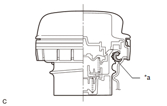
| (a) Visually check that the fuel tank cap assembly and gasket are not deformed or damaged. If the result is not as specified, replace the fuel tank cap assembly. |
|
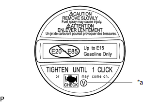
| (b) Confirm that ID mark V is printed on the fuel tank cap assembly. CAUTION: Make sure to use a fuel tank cap assembly that has the same ID mark, or a malfunction may occur in the fuel system. |
|
READ NEXT:
 Pcv Valve
ComponentsCOMPONENTS ILLUSTRATION
*1 PCV VALVE (VENTILATION VALVE SUB-ASSEMBLY)
*2 V-BANK COVER SUB-ASSEMBLY
*3 VENTILATION HOSE
- -
N*m (kgf*cm, f
Purge Valve
ComponentsCOMPONENTS ILLUSTRATION
*1 PURGE VALVE (PURGE VSV)
*2 V-BANK COVER SUB-ASSEMBLY
*3 FUEL VAPOR FEED HOSE
*4 NO. 1 FUEL VAPOR FEED HOSE
N*m
SEE MORE:
Riding with children
Observe the following precautions when children are in the vehicle.
Use a child restraint system appropriate for the child, until the
child becomes large enough to properly wear the vehicle's seat
belt.
It is recommended that children sit in the rear seats to avoid
accidental
contact w
Camshaft Position Sensor "A" Bank 1 or Single Sensor Circuit Short to Ground (P034011,P034015,P034511,P034515)
DESCRIPTION The VVT sensor (for intake camshaft) (VV1, VV2 signal) consists of a magnet and MRE (Magneto Resistance Element).
The intake camshaft has a timing rotor for the VVT sensor. When the intake camshaft rotates, changes occur in the air gaps between the timing rotor and MRE, which affects t
© 2023-2025 Copyright www.tocamry.com
