Toyota Camry (XV70): Indicator (Green) Circuit Short to Ground (B157111,B157113)
DESCRIPTION
This DTC is set when the DCM (telematics transceiver) detects an open or short in the manual (SOS) switch green indicator circuit of the manual (SOS) switch. The manual (SOS) switch green indicator illuminates after the engine switch is turned on (IG).
If the safety connect system is not active, the manual (SOS) switch green indicator will turn off.
If the safety connect system is active, the manual (SOS) switch green indicator will blink while communicating with the call center.
|
DTC No. | Detection Item |
DTC Detection Condition | Trouble Area |
|---|---|---|---|
|
B157111 | Indicator (Green) Circuit Short to Ground |
Manual (SOS) switch green indicator impedance (Ω) is lower than the malfunction threshold for 10 seconds or more when the engine switch is on (IG) |
|
| B157113 |
Indicator (Green) Circuit Open |
Manual (SOS) switch green indicator impedance (Ω) is higher than the malfunction threshold for 10 seconds or more when the engine switch is on (IG) |
|
WIRING DIAGRAM
w/ Sliding Roof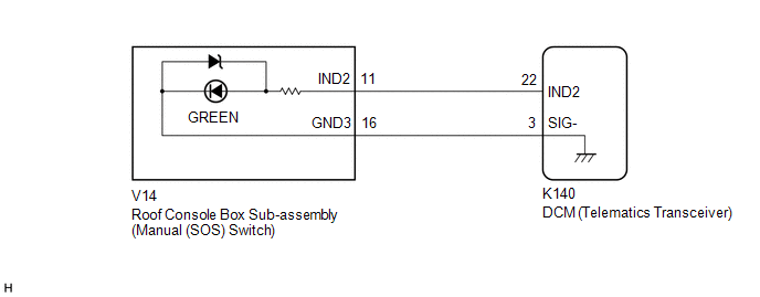 w/o Sliding Roof
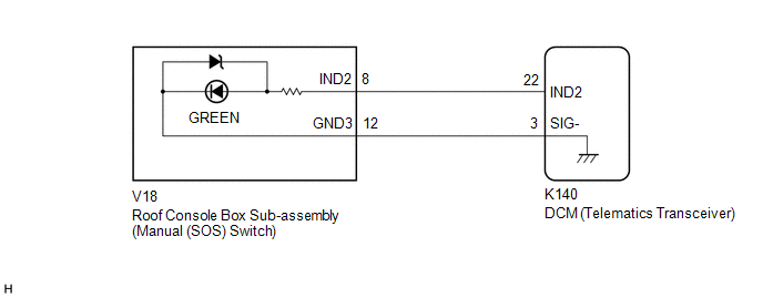
CAUTION / NOTICE / HINT
NOTICE:
Depending on the parts that are replaced during vehicle inspection or maintenance, performing initialization, registration or calibration may be needed. Refer to Precaution for Safety Connect System.
Click here .gif)
PROCEDURE
| 1. |
CHECK DTC |
(a) Turn the engine switch off.
(b) Connect the Techstream to the DLC3.
(c) Turn the engine switch on (IG) and wait for 10 seconds or more.
(d) Turn the Techstream on.
(e) Clear the DTCs.
Body Electrical > Telematics > Clear DTCs(f) Check for DTCs and check that no DTCs are output.
Body Electrical > Telematics > Trouble CodesOK:
No DTCs are output.
| OK | .gif) |
USE SIMULATION METHOD TO CHECK |
|
.gif)
| 2. |
CONFIRM MODEL |
(a) Choose the model to be inspected.
| Result |
Proceed to |
|---|---|
| w/ Sliding Roof |
A |
| w/o Sliding Roof |
B |
| B |
| GO TO STEP 5 |
|
| 3. |
INSPECT ROOF CONSOLE BOX SUB-ASSEMBLY (MANUAL (SOS) SWITCH) (GREEN INDICATOR) |
| (a) Remove the roof console box sub-assembly (manual (SOS) switch). Click here |
|
(b) Connect 2 dry-cell batteries (1.5 V each) in series.
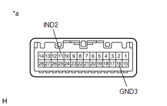
(c) Connect a positive (+) lead from batteries to terminal 11 (IND2) and a negative (-) lead to terminal 16 (GND3) of the roof console box sub-assembly (manual (SOS) switch) connector.
(d) Check if the manual (SOS) switch green indicator comes on.
OK:
Manual (SOS) switch green indicator illuminates.
| NG | | REPLACE ROOF CONSOLE BOX SUB-ASSEMBLY (MANUAL (SOS) SWITCH) |
|
| 4. |
CHECK HARNESS AND CONNECTOR (DCM (TELEMATICS TRANSCEIVER) - ROOF CONSOLE BOX SUB-ASSEMBLY (MANUAL (SOS) SWITCH)) |
(a) Disconnect the K140 DCM (telematics transceiver) connector.
(b) Disconnect the V14 roof console box sub-assembly (manual (SOS) switch) connector.
(c) Measure the resistance according to the value(s) in the table below.
Standard Resistance:
|
Tester Connection | Condition |
Specified Condition |
|---|---|---|
|
K140-22 (IND2) - V14-11 (IND2) |
Always | Below 1 Ω |
|
K140-22 (IND2) or V14-11 (IND2) - Body ground |
Always | 10 kΩ or higher |
|
K140-3 (SIG-) - V14-16 (GND3) |
Always | Below 1 Ω |
|
K140-3 (SIG-) or V14-16 (GND3) - Body ground |
Always | 10 kΩ or higher |
| OK | | GO TO STEP 7 |
| NG | | REPAIR OR REPLACE HARNESS OR CONNECTOR |
| 5. |
INSPECT ROOF CONSOLE BOX SUB-ASSEMBLY (MANUAL (SOS) SWITCH) (GREEN INDICATOR) |
| (a) Remove the roof console box sub-assembly (manual (SOS) switch). Click here |
|
(b) Connect 2 dry-cell batteries (1.5 V each) in series.
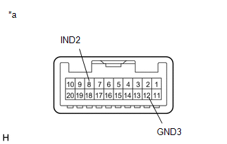
(c) Connect a positive (+) lead from batteries to terminal 8 (IND2) and a negative (-) lead to terminal 12 (GND3) of the roof console box sub-assembly (manual (SOS) switch) connector.
(d) Check if the manual (SOS) switch green indicator comes on.
OK:
Manual (SOS) switch green indicator illuminates.
| NG | | REPLACE ROOF CONSOLE BOX SUB-ASSEMBLY (MANUAL (SOS) SWITCH) |
|
| 6. |
CHECK HARNESS AND CONNECTOR (DCM (TELEMATICS TRANSCEIVER) - ROOF CONSOLE BOX SUB-ASSEMBLY (MANUAL (SOS) SWITCH)) |
(a) Disconnect the K140 DCM (telematics transceiver) connector.
(b) Disconnect the V18 roof console box sub-assembly (manual (SOS) switch) connector.
(c) Measure the resistance according to the value(s) in the table below.
Standard Resistance:
|
Tester Connection | Condition |
Specified Condition |
|---|---|---|
|
K140-22 (IND2) - V18-8 (IND2) |
Always | Below 1 Ω |
|
K140-22 (IND2) or V18-8 (IND2) - Body ground |
Always | 10 kΩ or higher |
|
K140-3 (SIG-) - V18-12 (GND3) |
Always | Below 1 Ω |
|
K140-3 (SIG-) or V18-12 (GND3) - Body ground |
Always | 10 kΩ or higher |
| NG | | REPAIR OR REPLACE HARNESS OR CONNECTOR |
|
| 7. |
REPLACE DCM (TELEMATICS TRANSCEIVER) |
(a) Replace the DCM (telematics transceiver) with a new one.
Click here
NOTICE:
- The engine switch must be off.
- Do not exchange the DCM (telematics transceiver) with one from another vehicle.
| NEXT | | PERFORM DCM ACTIVATION |
READ NEXT:
 Microphone Circuit Open (B157213)
DESCRIPTION This DTC is stored when the DCM (telematics transceiver) detects a malfunction in the telephone microphone assembly circuit.
DTC No. Detection Item
DTC Detection Condition T
DCM System Internal Failure (B15A804)
DESCRIPTION This DTC is stored when an internal circuit malfunction is detected by the DCM (telematics transceiver) self check.
DTC No. Detection Item
DTC Detection Condition Trouble Ar
GNSS Antenna Circuit Short to Ground (B15C111,B15C113)
DESCRIPTION These DTCs are stored when a malfunction occurs in the telephone and GPS antenna (for Roof Side) circuit.
DTC No. Detection Item
DTC Detection Condition Trouble Area
SEE MORE:
Precaution
PRECAUTION INITIALIZATION NOTICE: Make sure to perform the necessary procedures (adjustment, calibration, initialization, or registration) after parts related to the cooling fan system have been removed/installed or replaced.
Click here
Installation
INSTALLATION PROCEDURE 1. INSTALL FUEL PUMP CONTROL ECU BRACKET
(a) Install the fuel pump control ECU bracket to the fuel pump control ECU with the 2 bolts.
Torque: 4.5 N·m {46 kgf·cm, 40 in·lbf} 2. INSTALL FUEL PUMP CONTROL ECU
(a) Install the fuel pump control ECU to the vehicle body wit
