Toyota Camry (XV70): Microphone Circuit Open (B157213)
DESCRIPTION
This DTC is stored when the DCM (telematics transceiver) detects a malfunction in the telephone microphone assembly circuit.
|
DTC No. | Detection Item |
DTC Detection Condition | Trouble Area |
|---|---|---|---|
|
B157213 | Microphone Circuit Open |
Current at terminal MCVD is lower than the malfunction threshold for 10 seconds or more while the engine switch is on (IG) |
|
WIRING DIAGRAM
w/ Sliding Roof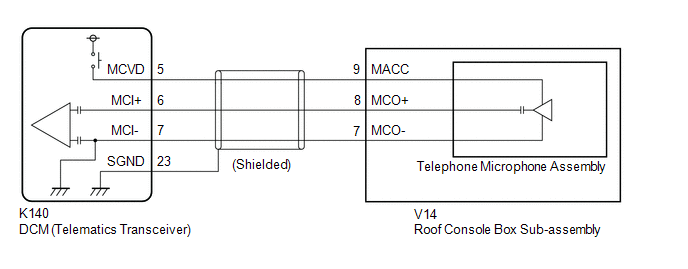 w/o Sliding Roof
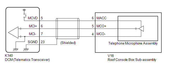
CAUTION / NOTICE / HINT
NOTICE:
Depending on the parts that are replaced during vehicle inspection or maintenance, performing initialization, registration or calibration may be needed. Refer to Precaution for Safety Connect System.
Click here .gif)
PROCEDURE
| 1. |
CHECK DTC |
(a) Turn the engine switch off.
(b) Connect the Techstream to the DLC3.
(c) Turn the engine switch on (IG) and wait for 10 seconds or more.
(d) Turn the Techstream on.
(e) Clear the DTCs.
Body Electrical > Telematics > Clear DTCs(f) Check for DTCs and check that no DTCs are output.
Body Electrical > Telematics > Trouble CodesOK:
No DTCs are output.
| OK | .gif) |
USE SIMULATION METHOD TO CHECK |
|
.gif)
| 2. |
CONFIRM MODEL |
(a) Choose the model to be inspected.
| Result |
Proceed to |
|---|---|
| w/ Sliding Roof |
A |
| w/o Sliding Roof |
B |
| B |
| GO TO STEP 5 |
|
| 3. |
CHECK HARNESS AND CONNECTOR (DCM (TELEMATICS TRANSCEIVER) - ROOF CONSOLE BOX SUB-ASSEMBLY) |
(a) Disconnect the K140 DCM (telematics transceiver) connector.
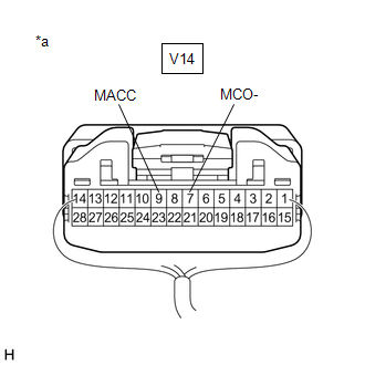
(b) Disconnect the V14 roof console box sub-assembly connector.
(c) Measure the resistance according to the value(s) in the table below.
Standard Resistance:
|
Tester Connection | Condition |
Specified Condition |
|---|---|---|
|
K140-5 (MCVD) - V14-9 (MACC) |
Always | Below 1 Ω |
|
K140-6 (MCI+) - V14-8 (MCO+) |
Always | Below 1 Ω |
|
K140-7 (MCI-) - V14-7 (MCO-) |
Always | Below 1 Ω |
|
K140-23 (SGND) - Body ground |
Always | 10 kΩ or higher |
|
K140-5 (MCVD) or V14-9 (MACC) - Body ground |
Always | 10 kΩ or higher |
|
K140-6 (MCI+) or V14-8 (MCO+) - Body ground |
Always | 10 kΩ or higher |
|
K140-7 (MCI-) or V14-7 (MCO-) - Body ground |
Always | 10 kΩ or higher |
| NG | | REPAIR OR REPLACE HARNESS OR CONNECTOR |
|
| 4. |
CHECK DCM (TELEMATICS TRANSCEIVER) (TELEPHONE MICROPHONE ASSEMBLY POWER SOURCE) |
| (a) Remove the telephone microphone assembly but do not disconnect the connectors. Click here |
|
(b) Measure the voltage and resistance according to the value(s) in the table below.
Standard Voltage:
|
Tester Connection | Switch Condition |
Specified Condition |
|---|---|---|
|
V14-9 (MACC) - Body ground |
Engine switch on (ACC) |
4 to 6 V |
Standard Resistance:
|
Tester Connection | Condition |
Specified Condition |
|---|---|---|
|
V14-7 (MCO-) - Body ground |
Always | Below 1 Ω |
| OK | | REPLACE TELEPHONE MICROPHONE ASSEMBLY |
| NG | | GO TO STEP 7 |
| 5. |
CHECK HARNESS AND CONNECTOR (DCM (TELEMATICS TRANSCEIVER) - ROOF CONSOLE BOX SUB-ASSEMBLY) |
(a) Disconnect the K140 DCM (telematics transceiver) connector.
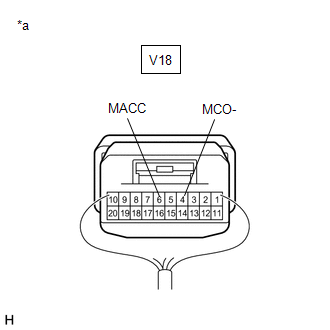
(b) Disconnect the V18 roof console box sub-assembly connector.
(c) Measure the resistance according to the value(s) in the table below.
Standard Resistance:
|
Tester Connection | Condition |
Specified Condition |
|---|---|---|
|
K140-5 (MCVD) - V18-6 (MACC) |
Always | Below 1 Ω |
|
K140-6 (MCI+) - V18-5 (MCO+) |
Always | Below 1 Ω |
|
K140-7 (MCI-) - V18-4 (MCO-) |
Always | Below 1 Ω |
|
K140-23 (SGND) - Body ground |
Always | 10 kΩ or higher |
|
K140-5 (MCVD) or V18-6 (MACC) - Body ground |
Always | 10 kΩ or higher |
|
K140-6 (MCI+) or V18-5 (MCO+) - Body ground |
Always | 10 kΩ or higher |
|
K140-7 (MCI-) or V18-4 (MCO-) - Body ground |
Always | 10 kΩ or higher |
| NG | | REPAIR OR REPLACE HARNESS OR CONNECTOR |
|
| 6. |
CHECK DCM (TELEMATICS TRANSCEIVER) (TELEPHONE MICROPHONE ASSEMBLY POWER SOURCE) |
| (a) Remove the roof console box sub-assembly but do not disconnect the connectors. Click here |
|
(b) Measure the voltage and resistance according to the value(s) in the table below.
Standard Voltage:
|
Tester Connection | Switch Condition |
Specified Condition |
|---|---|---|
|
V18-6 (MACC) - Body ground |
Engine switch on (ACC) |
4 to 6 V |
Standard Resistance:
|
Tester Connection | Condition |
Specified Condition |
|---|---|---|
|
V18-4 (MCO-) - Body ground |
Always | Below 1 Ω |
| OK | | REPLACE TELEPHONE MICROPHONE ASSEMBLY |
|
| 7. |
REPLACE DCM (TELEMATICS TRANSCEIVER) |
(a) Replace the DCM (telematics transceiver) with a new one.
Click here
NOTICE:
- The engine switch must be off
- Do not exchange the DCM (telematics transceiver) with one from another vehicle.
| NEXT | | PERFORM DCM ACTIVATION |
READ NEXT:
 DCM System Internal Failure (B15A804)
DESCRIPTION This DTC is stored when an internal circuit malfunction is detected by the DCM (telematics transceiver) self check.
DTC No. Detection Item
DTC Detection Condition Trouble Ar
GNSS Antenna Circuit Short to Ground (B15C111,B15C113)
DESCRIPTION These DTCs are stored when a malfunction occurs in the telephone and GPS antenna (for Roof Side) circuit.
DTC No. Detection Item
DTC Detection Condition Trouble Area
Airbag Signal Signal Plausibility Failure (B15C464)
DESCRIPTION If the DCM (telematics transceiver) detects an error in communication between the DCM (telematics transceiver) and the airbag sensor assembly as a result of the DCM (telematics transceiver
SEE MORE:
Components
COMPONENTS ILLUSTRATION
*A for 7 Inch Display
*B for 9 Inch Display
*C w/o Manual (SOS) Switch
*D w/ Manual (SOS) Switch
*1 CENTER INSTRUMENT CLUSTER FINISH PANEL ASSEMBLY
*2 CENTER INSTRUMENT CLUSTER FINISH PANEL SUB-ASSEMBLY
*3 INST
System Description
SYSTEM DESCRIPTION OPERATION OF OUTER REAR VIEW MIRROR INDICATOR AND RCTA BUZZER (BLIND SPOT MONITOR BUZZER)
(a) Initial check (1) When the blind spot monitor system is turned on with the engine switch on (IG), the outer rear view mirror indicators on the outer rear view mirror assembly with cover
