Toyota Camry (XV70): Inspection
INSPECTION
PROCEDURE
1. INSPECT FRONT NO. 2 SPEAKER ASSEMBLY (for 6 Speakers)
(a) With the speaker installed, check that there is no looseness or other abnormalities.
(b) Check that there is no foreign matter in the speaker, no tears on the speaker cone or other abnormalities.
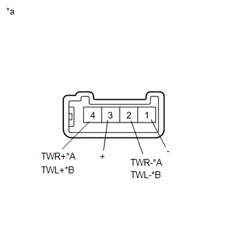
| (c) Measure the resistance of the speaker. Standard Resistance: for RH
If the result is not as specified, replace the speaker. |
|
(d) When there is a possibility that either the right or left speaker is malfunctioning, interchange the speakers and perform an inspection. If the malfunction disappears after interchanging the speakers, replace the malfunctioning speaker.
HINT:
Connect all connectors to the speakers when performing an inspection. If the result is not as specified, replace the speaker.
2. INSPECT FRONT NO. 2 SPEAKER ASSEMBLY (for 9 Speakers)
(a) With the speaker installed, check that there is no looseness or other abnormalities.
(b) Check that there is no foreign matter in the speaker, no tears on the speaker cone or other abnormalities.
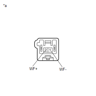
| (c) Measure the resistance of the speaker. Standard Resistance:
If the result is not as specified, replace the speaker. |
|
READ NEXT:
 Installation
INSTALLATION CAUTION / NOTICE / HINT
HINT:
Use the same procedure for the RH side and LH side.
The following procedure is for the LH side.
PROCEDURE 1. INSTALL FRONT NO. 2 SPEAKER ASSEMB
Microphone
ComponentsCOMPONENTS ILLUSTRATION
*A for Normal Roof
*B except Normal Roof
*1 ROOF CONSOLE BOX ASSEMBLY
*2 TELEPHONE MICROPHONE ASSEMBLY
*3 ROOF CONSOLE
SEE MORE:
Installation
INSTALLATION CAUTION / NOTICE / HINT
NOTICE:
Because the left and right front flexible hoses are not interchangeable, verify the part number when installing the front flexible hoses.
When reusing the front flexible hoses, use the identification marks created during removal to install each
ABS Operates Before Necessary When Braking
DESCRIPTION Troubleshooting for when ABS operates too soon due to a noisy signal from the speed sensor, a difference in output, etc. CAUTION / NOTICE / HINT
NOTICE:
After replacing or removing and installing a speed sensor, perform Dealer Mode (Signal Check) inspection to confirm that the spee
