Toyota Camry (XV70): Microphone
Components
COMPONENTS
ILLUSTRATION
|
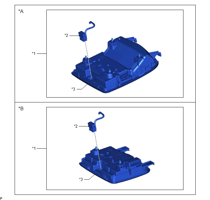
*A | for Normal Roof |
*B | except Normal Roof |
|
*1 | ROOF CONSOLE BOX ASSEMBLY |
*2 | TELEPHONE MICROPHONE ASSEMBLY |
|
*3 | ROOF CONSOLE BOX SUB-ASSEMBLY |
- | - |
Removal
REMOVAL
PROCEDURE
1. REMOVE ROOF CONSOLE BOX ASSEMBLY
Click here
.gif)
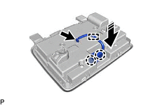
2. REMOVE TELEPHONE MICROPHONE ASSEMBLY
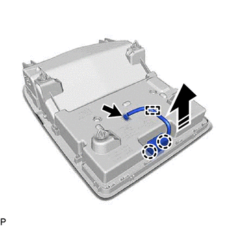
(a) for Normal Roof:
(1) Disconnect the connector.
 |
Remove in this Direction |
(2) Disengage the clamp.
(3) Disengage the 2 claws and remove the telephone microphone assembly from the roof console box sub-assembly as shown in the illustration.
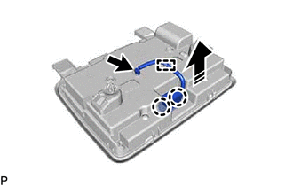
(b) except Normal Roof:
(1) Disconnect the connector.
|
|
Remove in this Direction |
(2) Disengage the clamp.
(3) Disengage the 2 claws and remove the telephone microphone assembly from the roof console box sub-assembly as shown in the illustration.
Installation
INSTALLATION
PROCEDURE
1. INSTALL TELEPHONE MICROPHONE ASSEMBLY
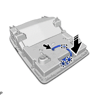
(a) for Normal Roof:
(1) Engage the 2 claws to install the telephone microphone assembly to the roof console box sub-assembly as shown in the illustration.
.png) |
Install in this Direction |
(2) Engage the clamp.
(3) Connect the connector.
(b) except Normal Roof:
(1) Engage the 2 claws to install the telephone microphone assembly to the roof console box sub-assembly as shown in the illustration.
|
|
Install in this Direction |
(2) Engage the clamp.
(3) Connect the connector.
2. INSTALL ROOF CONSOLE BOX ASSEMBLY
Click here .gif)
READ NEXT:
 Components
COMPONENTS ILLUSTRATION
*A for Fold Down Seat Type
- -
*1 REAR SEAT CUSHION ASSEMBLY
*2 REAR SEAT CUSHION LOCK HOOK
*3 REAR SIDE SEATBACK ASSEMBLY LH
On-vehicle Inspection
ON-VEHICLE INSPECTION PROCEDURE
1. INSPECT RADIO SETTING CONDENSER (for High Mounted Stop Light) (a) With the radio setting condenser installed, check that there is no looseness or other abnormaliti
SEE MORE:
Touch Panel Switch does not Function
CAUTION / NOTICE / HINT
NOTICE:
Depending on the parts that are replaced during vehicle inspection or maintenance, performing initialization, registration or calibration may be needed. Refer to Precaution for Navigation System.
Click here
When replacing the radio and display receiver
Yaw Rate Sensor Circuit Voltage Out of Range (C00631C)
DESCRIPTION The airbag sensor assembly has a built-in yaw rate and acceleration sensor and detects the vehicle condition.
The skid control ECU (brake actuator assembly) calibrates the sensitivity of the yaw rate sensor (airbag sensor assembly) based on signals from the steering angle sensor and sp
