Toyota Camry (XV70): On-vehicle Inspection
ON-VEHICLE INSPECTION
PROCEDURE
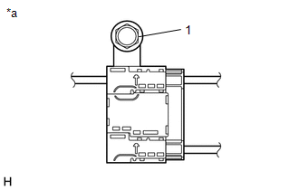
1. INSPECT RADIO SETTING CONDENSER (for High Mounted Stop Light)
(a) With the radio setting condenser installed, check that there is no looseness or other abnormalities.
| (b) Measure the resistance of the radio setting condenser according to the value(s) in the table below. Standard Resistance:
|
|
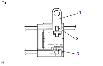
(c) Remove the bolt.
(d) Disengage the clamp and disconnect the radio setting condenser with wire harness from the vehicle body.
| (e) Measure the resistance and voltage of the radio setting condenser according to the value(s) in the table below. Standard Resistance:
Standard Voltage:
|
|
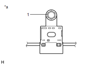
2. INSPECT RADIO SETTING CONDENSER (for Window Defogger)
(a) With the radio setting condenser installed, check that there is no looseness or other abnormalities.
| (b) Measure the resistance of the radio setting condenser according to the value(s) in the table below. Standard Resistance:
|
|
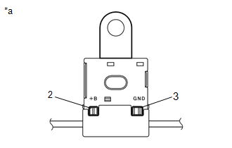
(c) Remove the bolt.
(d) Disengage the 2 clamps and disconnect the radio setting condenser with wire harness from the vehicle body.
| (e) Measure the resistance and voltage of the radio setting condenser according to the value(s) in the table below. Standard Resistance:
Standard Voltage:
|
|
READ NEXT:
 Removal
REMOVAL CAUTION / NOTICE / HINT
The necessary procedures (adjustment, calibration, initialization or registration) that must be performed after parts are removed and installed, or replaced during ra
Pillar Speaker
ComponentsCOMPONENTS ILLUSTRATION
*1 FRONT DOOR OPENING TRIM WEATHERSTRIP
*2 FRONT NO. 3 SPEAKER ASSEMBLY
*3 FRONT PILLAR GARNISH
*4 CLIP
● Non-re
SEE MORE:
Components
COMPONENTS ILLUSTRATION
*A w/o Manual (SOS) Switch
*B w/ Manual (SOS) Switch
*1 INSTRUMENT PANEL SAFETY PAD SUB-ASSEMBLY
*2 NAVIGATION ANTENNA ASSEMBLY
*3 NAVIGATION ANTENNA ASSEMBLY WITH BRACKET
*4 NAVIGATION ANTENNA BRACKET
*5 NO. 3
Left Front Wheel Speed Sensor Circuit Short to Ground or Open (C050014)
DESCRIPTION Refer to DTC C050012 Click here
DTC No. Detection Item
DTC Detection Condition Trouble Area
C050014 Left Front Wheel Speed Sensor Circuit Short to Ground or Open
A short or open circuit is detected in the speed sensor signal circuit for 0.12 seconds or
