Toyota Camry (XV70): Removal
REMOVAL
CAUTION / NOTICE / HINT
The necessary procedures (adjustment, calibration, initialization or registration) that must be performed after parts are removed and installed, or replaced during radio setting condenser removal/installation are shown below.
Necessary Procedure After Parts Removed/Installed/Replaced|
Replaced Part or Performed Procedure |
Necessary Procedures | Effect/Inoperative Function when Necessary Procedure not Performed |
Link |
|---|---|---|---|
| Disconnect cable from negative battery terminal |
Perform steering sensor zero point calibration |
Lane Tracing Assist System |
|
|
Pre-collision System | |||
|
Memorize steering angle neutral point |
Parking Assist Monitor System |
| |
|
Panoramic View Monitor System |
|
CAUTION:
Some of these service operations affect the SRS airbag system. Read the precautionary notices concerning the SRS airbag system before servicing.
.png)
Click here
.gif)
PROCEDURE
1. PRECAUTION
NOTICE:
After turning the ignition switch off, waiting time may be required before disconnecting the cable from the negative (-) battery terminal. Therefore, make sure to read the disconnecting the cable from the negative (-) battery terminal notices before proceeding with work.
Click here
2. DISCONNECT CABLE FROM NEGATIVE BATTERY TERMINAL
for A25A-FKS:
Click here
for 2GR-FKS:
Click here
CAUTION:
- Wait at least 90 seconds after disconnecting the cable from the negative (-) battery terminal to disable the SRS system.
- If an airbag deploys for any reason, it may cause a serious injury.
.png)
3. REMOVE REAR SEAT ASSEMBLY (for Fixed Seat Type)
Click here
4. REMOVE REAR SEAT CUSHION ASSEMBLY (for Fold Down Seat Type)
Click here
5. REMOVE REAR SEAT CUSHION LOCK HOOK (for Fold Down Seat Type)
Click here
6. DISCONNECT REAR DOOR OPENING TRIM WEATHERSTRIP LH
Click here
7. REMOVE REAR SIDE SEATBACK ASSEMBLY LH (for Fold Down Seat Type)
Click here
8. REMOVE INNER ROOF SIDE GARNISH LH
Click here
9. REMOVE RADIO SETTING CONDENSER (for High Mounted Stop Light)
NOTICE:
When a terminal cover is removed, the radio setting condenser must be replaced because the terminal covers and condenser are supplied as a set.
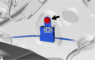
| (a) Remove the bolt. |
|
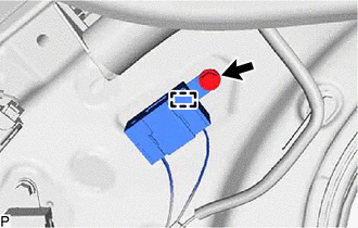
(b) Disengage the clamp and disconnect the radio setting condenser with wire harness from the vehicle body.
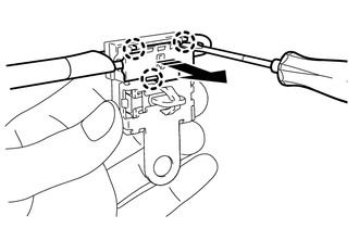
(c) Disengage the claw and pull out the cover as shown in the illustration.
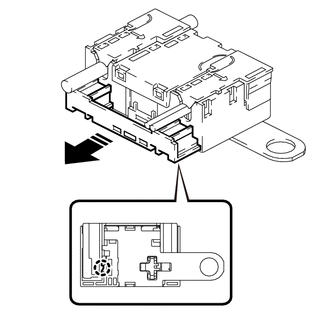
.png) |
Remove in this Direction |
(d) Using a screwdriver, disengage the 6 claws and remove the 2 terminal covers with wire harness from the condenser as shown in the illustration.
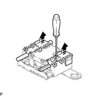
|
|
Remove in this Direction |
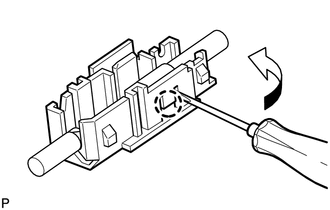
| (e) Using a screwdriver, bend back and break off the claw as shown in the illustration. HINT: Use the same procedure for the other terminal cover. |
|
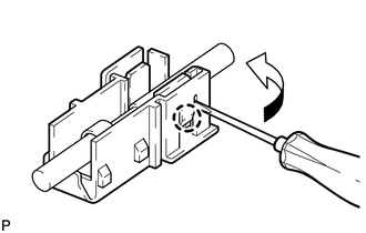
(f) Remove the 2 terminal covers from the wire harness.
NOTICE:
- Make sure to hold the crimping side of the terminal when disconnecting the wire harness from the terminal cover.
- Make sure not to bend the exposed wire when disconnecting the wire harness from the terminal cover.
- Check for deformation of the terminal after the wire harness has been removed from the terminal cover.
10. REMOVE RADIO SETTING CONDENSER (for Window Defogger)
NOTICE:
When the terminal cover is removed, the radio setting condenser must be replaced because the terminal cover and condenser are supplied as a set.
| (a) Remove the bolt. |
|
(b) Disengage the clamp and disconnect the radio setting condenser with wire harness from the vehicle body.
(c) Using a screwdriver, disengage the 3 claws and remove the terminal cover with wire harness from the condenser as shown in the illustration.
|
|
Remove in this Direction |
| (d) Using a screwdriver, bend back and break off the claw as shown in the illustration. |
|
(e) Remove the terminal cover from the wire harness.
NOTICE:
- Make sure to hold the crimping side of the terminal when disconnecting the wire harness from the terminal cover.
- Make sure not to bend the exposed wire when disconnecting the wire harness from the terminal cover.
- Check for deformation of the terminal after the wire harness has been removed from the terminal cover.
READ NEXT:
 Pillar Speaker
ComponentsCOMPONENTS ILLUSTRATION
*1 FRONT DOOR OPENING TRIM WEATHERSTRIP
*2 FRONT NO. 3 SPEAKER ASSEMBLY
*3 FRONT PILLAR GARNISH
*4 CLIP
● Non-re
Components
COMPONENTS ILLUSTRATION
*A w/o Navigation Antenna
*B w/ Navigation Antenna
*1 ANTENNA CORD SUB-ASSEMBLY
*2 INSTRUMENT PANEL SAFETY PAD SUB-ASSEMBLY
*3 N
SEE MORE:
AWD Warning does not Come ON
DESCRIPTION Refer to "4WD Warning Remains ON".
Click here WIRING DIAGRAM
Refer to "4WD Warning Remains ON". Click here
CAUTION / NOTICE / HINT
Refer to "4WD Warning Remains ON". Click here
PROCEDURE
1.
CHECK HARNESS AND CONNECTOR (a) Check that there is no looseness at
Removal
REMOVAL PROCEDURE 1. REMOVE V-BANK COVER SUB-ASSEMBLY
Click here
2. REMOVE CAMSHAFT TIMING OIL CONTROL SOLENOID ASSEMBLY (for Exhaust Side of Bank 2)
(a) Disconnect the camshaft timing oil control solenoid assembly connector.
(b) Remove the 2 bolts and camsha
