Toyota Camry (XV70): Components
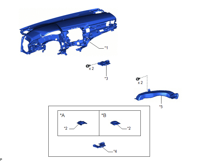
COMPONENTS
ILLUSTRATION
|
*A | w/o Manual (SOS) Switch |
*B | w/ Manual (SOS) Switch |
|
*1 | INSTRUMENT PANEL SAFETY PAD SUB-ASSEMBLY |
*2 | NAVIGATION ANTENNA ASSEMBLY |
|
*3 | NAVIGATION ANTENNA ASSEMBLY WITH BRACKET |
*4 | NAVIGATION ANTENNA BRACKET |
|
*5 | NO. 3 HEATER TO REGISTER DUCT SUB-ASSEMBLY |
- | - |
READ NEXT:
 Removal
REMOVAL CAUTION / NOTICE / HINT
The necessary procedures (adjustment, calibration, initialization, or registration) that must be performed after parts are removed and installed, or replaced during n
Inspection
INSPECTION PROCEDURE 1. INSPECT NAVIGATION ANTENNA ASSEMBLY (w/o Manual (SOS) Switch)
(a) Check that the navigation antenna assembly cable is properly installed and does not have any sharp bends, pi
Installation
INSTALLATION PROCEDURE 1. INSTALL NAVIGATION ANTENNA BRACKET
2. INSTALL NAVIGATION ANTENNA ASSEMBLY (a) Engage the 6 guides and 2 claws to install the navigation antenna assembly as shown in the ill
SEE MORE:
Freeze Frame Data
FREEZE FRAME DATA FREEZE FRAME DATA/INFORMATION
(a) Using the Techstream, check the vehicle condition (ECU, sensor) when the brake system operates or a DTC is output.
CHECK FREEZE FRAME DATA AND INFORMATION WHEN DTC WAS STORED (a) Freeze Frame Data is stored when a DTC is output.
(b) Once Free
Installation
INSTALLATION CAUTION / NOTICE / HINT
HINT:
Use the same procedure for the RH side and LH side.
The following procedure is for the LH side.
PROCEDURE 1. INSTALL FRONT AXLE HUB SUB-ASSEMBLY
(a) Secure the steering knuckle between aluminum plates in a vise. NOTICE:
Do not overtighten
© 2023-2025 Copyright www.tocamry.com
