Toyota Camry (XV70): Inspection
INSPECTION
PROCEDURE
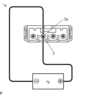
1. INSPECT NAVIGATION ANTENNA ASSEMBLY (w/o Manual (SOS) Switch)
(a) Check that the navigation antenna assembly cable is properly installed and does not have any sharp bends, pinching or loose connections.
(b) Current consumption check:
| (1) Measure the current consumption according to the value(s) in the table below. Standard Current:
NOTICE: Do not apply 6 V or more between terminals 3 and 3a. HINT: If a stable power supply is not available, connect 4 nickel-metal hydride batteries (1.2 V each) or equivalent in series. |
|
2. INSPECT NAVIGATION ANTENNA ASSEMBLY (w/ Manual (SOS) Switch)
(a) Check that the navigation antenna assembly cable is properly installed and does not have any sharp bends, pinching or loose connections.
(b) Current consumption check: (GPS)
| (1) Measure the current consumption according to the value(s) in the table below. Standard Current:
NOTICE: Do not apply 6 V or more between terminals 3 and 3a. HINT: If a stable power supply is not available, connect 4 nickel-metal hydride batteries (1.2 V each) or equivalent in series. |
|
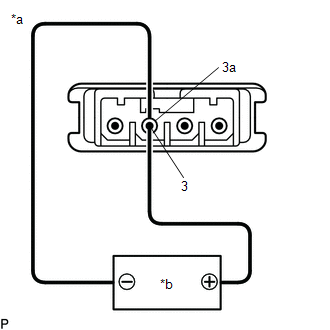
(c) Resistance check: (Telephone Sub)
| (1) Measure the resistance according to the value(s) in the table below. Standard Resistance:
|
|
READ NEXT:
 Installation
INSTALLATION PROCEDURE 1. INSTALL NAVIGATION ANTENNA BRACKET
2. INSTALL NAVIGATION ANTENNA ASSEMBLY (a) Engage the 6 guides and 2 claws to install the navigation antenna assembly as shown in the ill
Components
COMPONENTS ILLUSTRATION
*A for 7 Inch Display
*B for 9 Inch Display
*C w/o Manual (SOS) Switch
*D w/ Manual (SOS) Switch
*1 CENTER INSTRUMENT CLUSTER FI
SEE MORE:
Do-it-yourself service
precautions
If you perform maintenance by yourself, be sure to follow the
correct procedure as given in these sections.
WARNING
The engine compartment contains many mechanisms and fluids that may
move suddenly, become hot, or become electrically energized. To avoid death
or serious injury, observe the fo
Inspection
INSPECTION PROCEDURE 1. INSPECT VSC OFF SWITCH
(a) Make sure that there is no looseness at the locking part and the connecting part of the connector.
OK: The connector is securely connected.
*a Component without harness connected
(VSC OFF switch)
