Toyota Camry (XV70): Removal
REMOVAL
CAUTION / NOTICE / HINT
The necessary procedures (adjustment, calibration, initialization, or registration) that must be performed after parts are removed and installed, or replaced during navigation antenna assembly removal/installation are shown below.
Necessary Procedure After Parts Removed/Installed/Replaced|
Replaced Part or Performed Procedure |
Necessary Procedures | Effect/Inoperative Function when Necessary Procedure not Performed |
Link |
|---|---|---|---|
| Disconnect cable from negative battery terminal |
Perform steering sensor zero point calibration |
Lane Tracing Assist System |
|
|
Pre-collision System | |||
|
Memorize steering angle neutral point |
Parking Assist Monitor System |
| |
|
Panoramic View Monitor System |
|
CAUTION:
Some of these service operations affect the SRS airbag system. Read the precautionary notices concerning the SRS airbag system before servicing.
Click here .gif)
.png)
PROCEDURE
1. REMOVE INSTRUMENT PANEL SAFETY PAD SUB-ASSEMBLY
Click here
2. REMOVE NO. 3 HEATER TO REGISTER DUCT SUB-ASSEMBLY
Click here
3. REMOVE NAVIGATION ANTENNA ASSEMBLY WITH BRACKET
| (a) Disconnect the connector. |
|
.png)
(b) Disengage the 2 claws.
| (c) Remove the 2 screws and navigation antenna assembly with bracket. |
|
.png)
4. REMOVE NAVIGATION ANTENNA ASSEMBLY
(a) Disengage the 2 claws and 6 guides to remove the navigation antenna assembly as shown in the illustration.
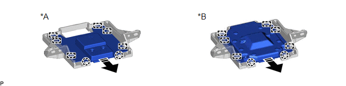
|
*A | w/o Manual (SOS) Switch |
*B | w/ Manual (SOS) Switch |
.png) |
Remove in this Direction |
- | - |
5. REMOVE NAVIGATION ANTENNA BRACKET
READ NEXT:
 Inspection
INSPECTION PROCEDURE 1. INSPECT NAVIGATION ANTENNA ASSEMBLY (w/o Manual (SOS) Switch)
(a) Check that the navigation antenna assembly cable is properly installed and does not have any sharp bends, pi
Installation
INSTALLATION PROCEDURE 1. INSTALL NAVIGATION ANTENNA BRACKET
2. INSTALL NAVIGATION ANTENNA ASSEMBLY (a) Engage the 6 guides and 2 claws to install the navigation antenna assembly as shown in the ill
SEE MORE:
Components
COMPONENTS ILLUSTRATION
*1 AIR CLEANER ASSEMBLY WITH AIR CLEANER HOSE
*2 COOL AIR INTAKE DUCT SEAL
*3 INLET AIR CLEANER ASSEMBLY
*4 VACUUM SWITCHING VALVE (for Active Control Engine Mount System)
*5 VACUUM HOSE
*6 ENGINE WIRE
*7 NO. 1
Components
COMPONENTS ILLUSTRATION
*1 FRONT FLOOR COVER LH
*2 FRONT FLOOR COVER RH
N*m (kgf*cm, ft.*lbf): Specified torque
- - ILLUSTRATION
*1 BODY MOUNTING PLATE
*2 NO. 1 ENGINE UNDER COVER
*3 REAR ENGINE UNDER COVER RH
*4 FRO
