Toyota Camry (XV70): Inspection
INSPECTION
PROCEDURE
1. INSPECT COMBINATION SWITCH (ELECTRIC PARKING BRAKE SWITCH ASSEMBLY)
(a) Inspect the NORMAL mode switch:
| (1) Measure the resistance according to the value(s) in the table below. Standard Resistance:
If the result is not as specified, replace the combination switch (electric parking brake switch assembly). |
|
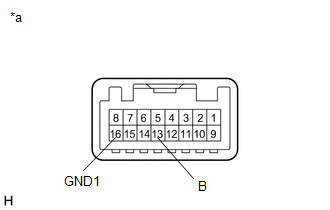
(b) Inspect the SPORT mode switch:
| (1) Measure the resistance according to the value(s) in the table below. Standard Resistance:
If the result is not as specified, replace the combination switch (electric parking brake switch assembly). |
|

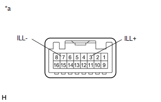
(c) Inspect the illumination:
| (1) Apply battery voltage to the combination switch (electric parking brake switch assembly) and check that the switch illuminates. OK:
If the result is not as specified, replace the combination switch (electric parking brake switch assembly). |
|
READ NEXT:
 Installation
INSTALLATION PROCEDURE 1. INSTALL COMBINATION SWITCH (ELECTRIC PARKING BRAKE SWITCH ASSEMBLY)
Click here 2. INSTALL REAR UPPER CONSOLE PANEL SUB-ASSEMBLY
Click here
3. INSTALL SHIFT LEVE
Components
COMPONENTS ILLUSTRATION
*1 FRONT DIFFERENTIAL CASE FRONT TAPERED ROLLER BEARING (INNER RACE)
*2 FRONT DIFFERENTIAL CASE FRONT TAPERED ROLLER BEARING (OUTER RACE)
*3 FRONT
SEE MORE:
Under Hood
UNDER HOOD GENERAL NOTES
Maintenance requirements vary depending on country.
Check the maintenance schedule in the owner's manual.
Following the maintenance schedule is mandatory.
Determine the appropriate time to service the vehicle using either miles driven or time (months) elapse
Relay
On-vehicle InspectionON-VEHICLE INSPECTION PROCEDURE
1. INSPECT NO. 1 ELECTRONIC FUEL INJECTION MAIN RELAY (EFI-MAIN NO. 1)
(a) Measure the resistance according to the value(s) in the table below.
Standard Resistance:
Tester Connection Condition
Specified Condition
