Toyota Camry (XV70): Left Electric Parking Brake Actuator Control Circuit Open (C060B13)
DESCRIPTION
|
DTC No. | Detection Item |
DTC Detection Condition | Trouble Area |
Memory | Note |
|---|---|---|---|---|---|
|
C060B13 | Left Electric Parking Brake Actuator Control Circuit Open |
|
| DTC stored |
An electric parking brake system malfunction is displayed on the multi-information display. |
WIRING DIAGRAM
Click here .gif)
PROCEDURE
| 1. |
INSPECT NO. 2 PARKING BRAKE WIRE ASSEMBLY |
(a) Turn the ignition switch off.
(b) Make sure that there is no looseness at the locking part and the connecting part of the connectors.
OK:
The connector is securely connected.
(c) Disconnect the vR2 and v1 No. 2 parking brake wire assembly connectors.
(d) Check both the connector case and the terminals for deformation and corrosion.
OK:
No deformation or corrosion.
(e) Measure the resistance according to the value(s) in the table below.
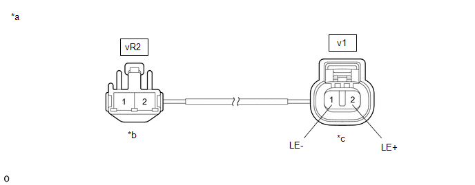
|
*a | Front view of No. 2 Parking Brake Wire Assembly |
*b | (to wire harness connector) |
|
*c | (to Parking Brake Actuator Assembly LH) |
- | - |
Standard Resistance:
|
Tester Connection | Condition |
Specified Condition |
|---|---|---|
|
vR2-2 - v1-2 (LE+) | Always |
Below 1 Ω |
|
vR2-2 - Other terminals |
Always | 10 kΩ or higher |
|
vR2-1 - v1-1 (LE-) | Always |
Below 1 Ω |
|
vR2-1 - Other terminals |
Always | 10 kΩ or higher |
| NG | .gif) | REPLACE NO. 2 PARKING BRAKE WIRE ASSEMBLY |
|
.gif)
| 2. |
CHECK HARNESS AND CONNECTOR (SKID CONTROL ECU (BRAKE ACTUATOR ASSEMBLY) - PARKING BRAKE ACTUATOR ASSEMBLY LH) |
(a) Turn the ignition switch off.
(b) Make sure the No. 2 parking brake wire assembly is securely installed.
(c) Disconnect the A34 skid control ECU (brake actuator assembly) connector.
(d) Disconnect the v1 parking brake actuator assembly LH connector.
(e) Measure the resistance according to the value(s) in the table below.
Standard Resistance:
|
Tester Connection | Condition |
Specified Condition |
|---|---|---|
|
A34-13 (MRL+) - v1-2 (LE+) |
Always | Below 1 Ω |
|
A34-12 (MRL-) - v1-1 (LE-) |
Always | Below 1 Ω |
| NG | | REPAIR OR REPLACE HARNESS OR CONNECTOR |
|
| 3. |
INSPECT PARKING BRAKE ACTUATOR ASSEMBLY LH |
(a) Remove the parking brake actuator assembly LH.
Click here
(b) Inspect the parking brake actuator assembly LH.
Click here
| OK | | REPLACE SKID CONTROL ECU (BRAKE ACTUATOR ASSEMBLY) |
| NG | | REPLACE PARKING BRAKE ACTUATOR ASSEMBLY LH |
READ NEXT:
 Left Electric Parking Brake Actuator Signal Stuck In Range (C060E2A)
DESCRIPTION
DTC No. Detection Item
DTC Detection Condition Trouble Area
Memory Note
C060E2A Left Electric Parking Brake Actuator Signal Stuck In Range
Diagno
Right Electric Parking Brake Actuator Control (C061000,C061011)
DESCRIPTION
DTC No. Detection Item
DTC Detection Condition Trouble Area
Memory Note
C061000 Right Electric Parking Brake Actuator Control
Diagnosis Condition
Right Electric Parking Brake Actuator Control Circuit Short to Battery (C061012)
DESCRIPTION
DTC No. Detection Item
DTC Detection Condition Trouble Area
Memory Note
C061012 Right Electric Parking Brake Actuator Control Circuit Short to Battery
SEE MORE:
Parts Location
PARTS LOCATION ILLUSTRATION
*1 OUTER REAR VIEW MIRROR ASSEMBLY WITH COVER RH
*2 OUTER REAR VIEW MIRROR ASSEMBLY WITH COVER LH
*3 BRAKE ACTUATOR ASSEMBLY - SKID CONTROL ECU
*4 ECM ILLUSTRATION
*1 OUTER MIRROR LH
*2 OUTER MIRROR RH
*
Removal
REMOVAL CAUTION / NOTICE / HINT
HINT:
Use the same procedure for the RH side and LH side.
The following procedure is for the LH side.
PROCEDURE 1. REMOVE REAR WHEEL Click here
2. DISCONNECT NO. 2 PARKING BRAKE WIRE ASSEMBLY
(a) Disconnect the No. 2 parking brake wire assembly
