Toyota Camry (XV70): Operation Check
OPERATION CHECK
PERFORM BLIND SPOT MONITOR BEAM AXIS CONFIRMATION
HINT:
The blind spot monitor beam axis confirmation is performed to confirm whether the sensor beam axis is correct, and to adjust the beam axis by using a reflector.
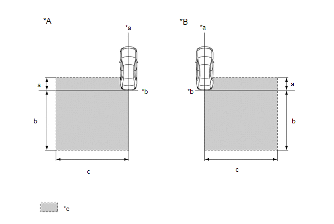
(a) When performing the blind spot monitor beam axis confirmation, move the vehicle to a place where the space shown in the illustration can be secured.
|
*A | Left Side of Vehicle |
*B | Right Side of Vehicle |
|
*a | Vehicle Center Line |
*b | Rear Bumper |
|
*c | Inspection Area |
- | - |
Standard:
|
Location | Measurement |
|---|---|
|
a | 1 m (3.28 ft.) |
|
b | 5 m (16.41 ft.) |
|
c | 6 m (19.68 ft.) |
NOTICE:
- Perform this inspection on level ground.
- Make sure that there are no metal objects around the vehicle or on the ground.
- Unload the vehicle before beginning the inspection.
- Confirm that the tire pressure is correct before beginning the inspection.
- Do not place any objects other than the reflector (such as a large metallic object) in the inspection area or allow people to enter the inspection area (W 6 m [19.68 ft.] x L 6 m [19.68 ft.] x H 4 m [13.12 ft.]) shown in the illustration.
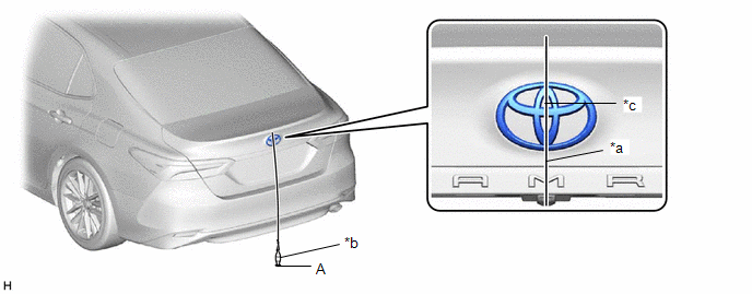
(b) Place the reflector.
(1) Hang a weight with a pointed tip from the center of the rear emblem, and mark the rear center point of the vehicle (point A) on the ground.
|
*a | String |
*b | Weight |
|
*c | Center |
- | - |
HINT:
Lightly flick the string with your fingers several times to confirm that the string is aligned with mark A.
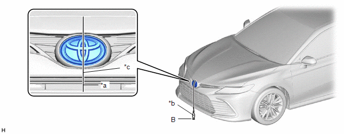
(2) Hang a weight with a pointed tip from the center of the radiator grille (or front panel) emblem, and mark the front center point of the vehicle (point B) on the ground.
|
*a | String |
*b | Weight |
|
*c | Center |
- | - |
HINT:
Lightly flick the string with your fingers several times to confirm that the string is aligned with mark B.
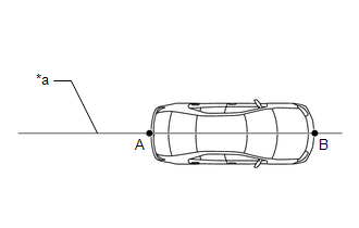
(3) Draw a vehicle center line so that it passes through mark A and B (front and rear center points).
|
*a | Vehicle Center Line |
(4) Enlarge and print out the poster shown in the illustration.
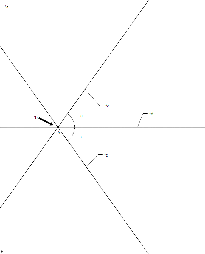
|
*a | Poster |
*b | Edge of Rear Bumper |
|
*c | Line C |
*d | Vehicle Center Line |
Standard:
|
Part | Angle |
|---|---|
|
a | 54.5 |
READ NEXT:
 Customize Parameters
CUSTOMIZE PARAMETERS CUSTOMIZE BLIND SPOT MONITOR SYSTEM
(a) Customizing with the Techstream
NOTICE:
When the customer requests a change in a function, first make sure that the function can be
Problem Symptoms Table
PROBLEM SYMPTOMS TABLE
HINT:
Use the table below to help determine the cause of problem symptoms. If multiple suspected areas are listed, the potential causes of the symptoms are listed in order
Terminals Of Ecu
TERMINALS OF ECU BLIND SPOT MONITOR SENSOR RH (MASTER)
Terminal No. (Symbol)
Wiring Color Terminal Description
Condition Specified Condition
W5-4 (OMIR) - W5-10 (BRGD)
SEE MORE:
Moon roof
Use the overhead switches to open and close the moon roof and
tilt it up and down.
Opening and closing
Opens the moon roof*
The moon roof stops slightly before
the fully open position to reduce
wind noise.
Press the switch again to fully open
the moon roof.
Closes the moon roof*
System Description
SYSTEM DESCRIPTION DESCRIPTION
Toyota Entune allows the vehicle to receive information from the call center and links the information to the audio and visual system*1 or navigation system*2. Toyota Entune permits the driver to use the received information, such as destination information, on th
