Toyota Camry (XV70): Parts Location
PARTS LOCATION
ILLUSTRATION
|
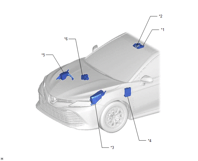
*1 | ROOF CONSOLE BOX SUB-ASSEMBLY |
*2 | TELEPHONE MICROPHONE ASSEMBLY |
|
*3 | ENGINE ROOM RELAY BLOCK AND JUNCTION BLOCK ASSEMBLY - TV FUSE (for 9 Inch Display Type) |
*4 | INSTRUMENT PANEL JUNCTION BLOCK ASSEMBLY - ECU-ACC FUSE - ECU-DCC NO. 2 FUSE - ECU-IG1 NO. 4 FUSE - ECU-IG2 NO. 3 FUSE (w/ Manual (SOS) Switch) - DCM FUSE (w/ Manual (SOS) Switch) - PANEL FUSE - METER-IG2 FUSE - RADIO FUSE (for 7 Inch Display Type) |
|
*5 | NO. 2 ENGINE ROOM RELAY BLOCK AND JUNCTION BLOCK ASSEMBLY - AMP NO. 1 FUSE (for 9 Speakers) - AMP NO. 2 FUSE (for 9 Speakers) |
*6 | SKID CONTROL ECU (BRAKE ACTUATOR ASSEMBLY) (for Electric Parking Brake System) |
ILLUSTRATION
|
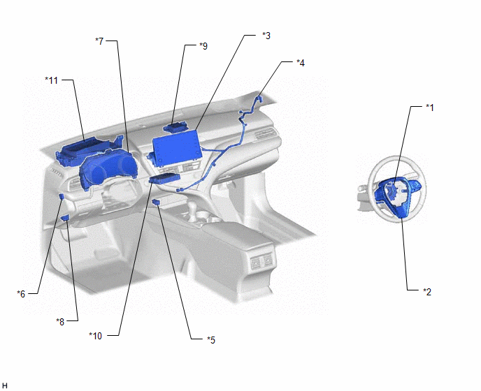
*1 | SPIRAL CABLE SUB-ASSEMBLY |
*2 | STEERING PAD SWITCH ASSEMBLY |
|
*3 | RADIO AND DISPLAY RECEIVER ASSEMBLY |
*4 | ANTENNA CORD SUB-ASSEMBLY (for Front Side) |
|
*5 | NO. 1 STEREO JACK ADAPTER ASSEMBLY |
*6 | PARKING BRAKE SWITCH ASSEMBLY (for Parking Brake Pedal Type) |
|
*7 | COMBINATION METER ASSEMBLY |
*8 | DLC3 |
|
*9 | NAVIGATION ANTENNA ASSEMBLY (w/ Navigation Antenna Assembly) - GPS | *10 |
DCM (TELEMATICS TRANSCEIVER) (w/ Manual (SOS) Switch) |
|
*11 | HEADUP DISPLAY (METER MIRROR SUB-ASSEMBLY) (w/ Headup Display System) |
- | - |
ILLUSTRATION
for 6 Speakers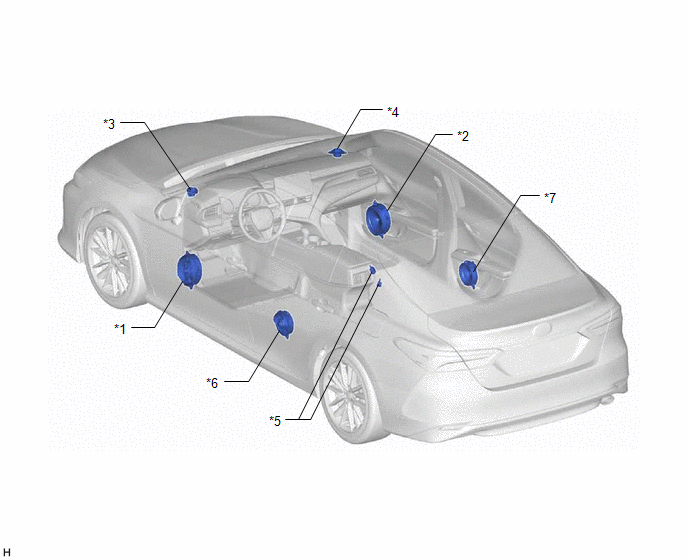
|
*1 | FRONT NO. 1 SPEAKER ASSEMBLY LH |
*2 | FRONT NO. 1 SPEAKER ASSEMBLY RH |
|
*3 | FRONT NO. 2 SPEAKER ASSEMBLY LH |
*4 | FRONT NO. 2 SPEAKER ASSEMBLY RH |
|
*5 | RADIO SETTING CONDENSER |
*6 | REAR SPEAKER ASSEMBLY LH |
|
*7 | REAR SPEAKER ASSEMBLY RH |
- | - |
ILLUSTRATION
for 9 Speakers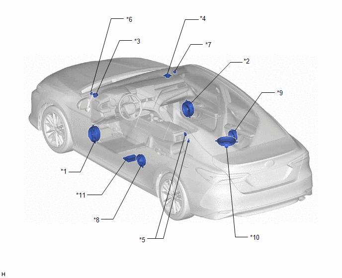
|
*1 | FRONT NO. 1 SPEAKER ASSEMBLY LH |
*2 | FRONT NO. 1 SPEAKER ASSEMBLY RH |
|
*3 | FRONT NO. 2 SPEAKER ASSEMBLY LH |
*4 | FRONT NO. 1 SPEAKER ASSEMBLY RH |
|
*5 | RADIO SETTING CONDENSER |
*6 | FRONT NO. 3 SPEAKER ASSEMBLY LH |
|
*7 | FRONT NO. 3 SPEAKER ASSEMBLY RH |
*8 | REAR SPEAKER ASSEMBLY LH |
|
*9 | REAR SPEAKER ASSEMBLY RH |
*10 | REAR STEREO COMPONENT SPEAKER ASSEMBLY |
|
*11 | STEREO COMPONENT AMPLIFIER ASSEMBLY |
- | - |
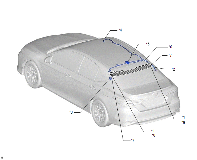
ILLUSTRATION
|
*1 | WINDOW GLASS ANTENNA WIRE |
*2 | NO. 1 AMPLIFIER ANTENNA ASSEMBLY |
|
*3 | NO. 2 AMPLIFIER ANTENNA ASSEMBLY |
*4 | NO. 2 ANTENNA CORD SUB-ASSEMBLY |
|
*5 | ROOF ANTENNA ASSEMBLY (w/ SXM Function) - SiriusXM | *6 |
NO. 5 ANTENNA CORD SUB-ASSEMBLY (w/ SXM Function) |
|
*7 | ANTENNA CORD SUB-ASSEMBLY (for Rear Side) |
*8 | - FM Sub |
|
*9 | - FM Main - AM |
- | - |
READ NEXT:
 System Description
SYSTEM DESCRIPTION USB AUDIO SYSTEM FUNCTION OUTLINE
(a) The No. 1 stereo jack adapter assembly is equipped with a USB connector. Connecting a USB device or "iPod" to the No. 1 stereo jack adapter a
How To Proceed With Troubleshooting
CAUTION / NOTICE / HINT
HINT:
Use the following procedure to troubleshoot the audio and visual system.
*: Use the Techstream.
PROCEDURE
1. VEHICLE BROUGHT TO WORKSHOP
Operation Check
OPERATION CHECK STORAGE CHECK
NOTICE:
When replacing the radio and display receiver assembly, always replace it with a new one. If a radio and display receiver assembly which was installed to an
SEE MORE:
Voice is not Recognized
PROCEDURE
1. CHECK CONDITION
(a) While paying attention to the condition of the spoken voice command, perform a voice recognition operation.
OK: Voice command is recognized normally.
HINT:
When the voice command is recognized, the content of the voice command is displayed in t
Inspection
INSPECTION PROCEDURE 1. INSPECT FUEL PUMP ASSEMBLY
(a) Measure the resistance according to the value(s) in the table below.
Standard Resistance:
Tester Connection Condition
Specified Condition
1 - 2 20°C (68°F)
0.45 to 0.55 Ω If the result is not
