Toyota Camry (XV70): Operation Check
OPERATION CHECK
STORAGE CHECK
NOTICE:
- When replacing the radio and display receiver assembly, always replace it with a new one. If a radio and display receiver assembly which was installed to another vehicle is used, the following may occur:
- A communication malfunction DTC may be stored.
- The radio and display receiver assembly may not operate normally.
HINT:
Illustrations may differ from the actual vehicle screen depending on the device settings and options. Therefore, some detailed areas may not be shown exactly the same as on the actual vehicle screen.
(a) Enter diagnostic mode.
Click here
.gif)
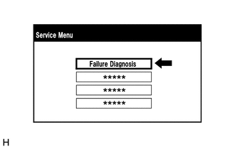
(b) Select "Failure Diagnosis" from the "Service Menu" screen.
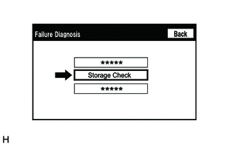
(c) Select "Storage Check" from the "Failure Diagnosis" screen.
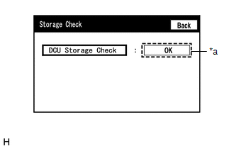
(d) Storage Check
|
*a | Result |
(1) Select "DCU Storage Check" to start the radio and display receiver assembly storage check.
(2) Check the result displayed when the radio and display receiver assembly storage check is complete.
Screen Description|
Display (Result) | Description |
|---|---|
|
Checking | Check is in progress |
|
OK | Radio and display receiver assembly storage is normal |
|
NG | Radio and display receiver assembly storage is malfunctioning |
HINT:
- After selecting "DCU Storage Check", it may take a while for the result to be displayed.
- If the cabin temperature is -20
READ NEXT:
 Problem Symptoms Table
PROBLEM SYMPTOMS TABLE
NOTICE:
Depending on the parts that are replaced during vehicle inspection or maintenance, performing initialization, registration or calibration may be needed. Refer to P
Terminals Of Ecu
TERMINALS OF ECU HINT: Check from the rear of the connector while it is connected to the components.
RADIO AND DISPLAY RECEIVER ASSEMBLY
Terminal No. (Symbol) Wiring Color
Terminal D
Dtc Check / Clear
DTC CHECK / CLEAR CHECK DTC (CHECK USING TECHSTREAM)
(a) Connect the Techstream to the DLC3. (b) Turn the ignition switch to ON and wait for 90 seconds.
(c) Turn the Techstream on. (d) Enter the f
SEE MORE:
Garage door opener
The garage door opener can be programmed to operate garage
doors, gates, entry doors, door locks, home lighting systems,
security systems, and other devices.
System components
The HomeLink wireless control system in your vehicle has 3 buttons
which can be programmed to operate 3 different devic
On-vehicle Inspection
ON-VEHICLE INSPECTION PROCEDURE
1. CONNECT TECHSTREAM (a) Connect the Techstream to the DLC3 with the ignition switch off.
(b) Start the engine and run it at idle. (c) Turn the Techstream on.
(d) Enter the following menus: Chassis / Brake / Active Test. HINT:
Refer to the Techstream operator
