Toyota Camry (XV70): Terminals Of Ecu
TERMINALS OF ECU
HINT:
Check from the rear of the connector while it is connected to the components.
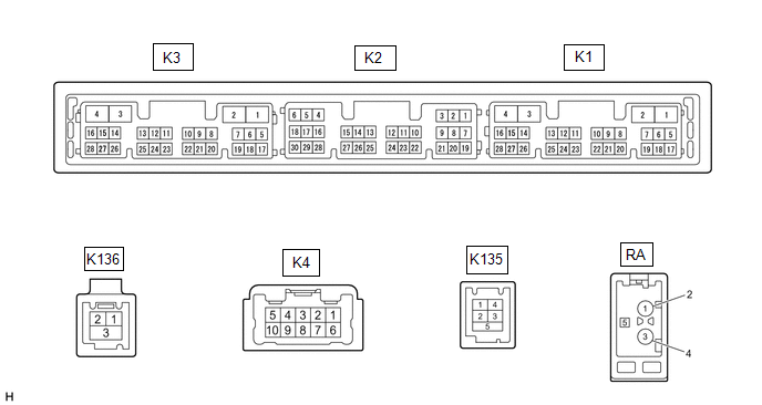
RADIO AND DISPLAY RECEIVER ASSEMBLY
|
Terminal No. (Symbol) | Wiring Color |
Terminal Description | Condition |
Specified Condition |
|---|---|---|---|---|
|
K4-1 (FR+) - K3-1 (GND1) |
LA-LG - BR*1 W - BR*2 |
Sound signal (Front right)*1 Sound signal (Right)*2 |
Audio system playing |
A waveform synchronized with sound signals is output |
|
K4-2 (FL+) - K3-1 (GND1) |
LA-B - BR*1 B - BR*2 |
Sound signal (Front left)*1 Sound signal (Left)*2 |
Audio system playing |
A waveform synchronized with sound signals is output |
|
K4-3 (RL+) - K3-1 (GND1) |
LA-G - BR*1 Y - BR*2 |
Sound signal (Rear left)*1 Voice signal*2 |
Audio system playing*1 Voice guidance sounding*2 |
A waveform synchronized with sound signals is output*1 A waveform synchronized with voice signals is output*2 |
|
K4-4 (RR+) - K3-1 (GND1)*1 |
LA-R - BR | Sound signal (Rear right) |
Audio system playing |
A waveform synchronized with sound signals is output |
|
K4-6 (FR-) - K3-1 (GND1) |
LA-L - BR*1 R - BR*2 |
Sound signal (Front right)*1 Sound signal (Right)*2 |
Audio system playing |
A waveform synchronized with sound signals is output |
|
K4-7 (FL-) - K3-1 (GND1) |
LA-R - BR*1 G - BR*2 |
Sound signal (Front left)*1 Sound signal (Left)*2 |
Audio system playing |
A waveform synchronized with sound signals is output |
|
K4-8 (RL-) - K3-1 (GND1) |
LA-GR - BR*1 BR - BR*2 |
Sound signal (Rear left)*1 Voice signal*2 |
Audio system playing |
A waveform synchronized with sound signals is output |
|
K4-9 (RR-) - K3-1 (GND1)*1 |
LA-G - BR | Sound signal (Rear right) |
Audio system playing |
A waveform synchronized with sound signals is output |
|
K3-1 (GND1) - Body ground |
BR - Body ground | Ground |
Always | Below 1 V |
|
K3-4 (+B1) - K3-1 (GND1) |
LG - BR*5 R - BR*8 |
Power source (+B) | Always |
11 to 14 V |
|
K3-5 (TX1+)*2 | B |
AVC-LAN communication signal |
- | - |
|
K3-6 (TX1-)*2 | W |
AVC-LAN communication signal |
- | - |
|
K3-15 (ACC1) - K3-1 (GND1) |
GR - BR | Power source (ACC) |
Ignition switch off | Below 1 V |
|
Ignition switch ACC | 11 to 14 V | |||
|
K3-21 (SW1) - K3-24 (SWG) |
W - L | Steering pad switch signal |
No switch pushed | 2.97 to 3.56 V |
|
Seek+ switch pushed | 0.27 to 0.35 V | |||
|
Seek- switch pushed | 0.86 to 1.03 V | |||
|
Up switch pushed | 0.27 to 0.35 V | |||
|
Down switch pushed | 0.86 to 1.03 V | |||
|
Volume+ switch pushed |
1.51 to 1.79 V | |||
|
Volume- switch pushed |
2.22 to 2.66 V | |||
|
K3-22 (SW2) - K3-24 (SWG) |
LG - L | Steering pad switch signal |
No switch pushed | 2.97 to 3.56 V |
|
MODE switch pushed | 0.27 to 0.35 V | |||
|
On/off hook switch pushed |
1.51 to 1.79 V | |||
|
Voice switch pushed | 2.22 to 2.66 V | |||
|
K3-24 (SWG) - K3-1 (GND1) |
L - BR | Steering pad switch ground |
Always | Below 1 V |
|
K3-25 (MUT1) - K3-1 (GND1)*2 |
BE - BR | Mute signal |
Audio system playing |
2.0 V or higher |
|
Audio system changing modes |
Below 1 V | |||
|
K3-27 (SPD) - K3-1 (GND1) |
LG - BR | Vehicle speed signal |
See "Check Vehicle Signal" in Operation Check Click here
|
- |
| K3-28 (REV) - K3-1 (GND1) |
W - BR | Reverse signal |
See "Check Vehicle Signal" in Operation Check Click here
|
- |
|
K2-3 (TMUT) - K3-1 (GND1)*3 |
BE - BR | Mute signal |
Audio system playing |
Above 2.0 V |
|
Emergency call mode | Below 1 V | |||
|
K2-5 (CNH1)*5 | L |
Local bus communication signal |
- | - |
|
K2-6 (CNL1)*5 | W |
Local bus communication signal |
- | - |
|
K2-13 (CANH) | B |
CAN communication signal |
- | - |
|
K2-14 (CANL) | W |
CAN communication signal |
- | - |
|
K2-15 (ILL+) - K3-1 (GND1) |
G - BR | Illumination signal |
Light control switch off |
Below 1 V |
|
Light control switch in tail or head position |
11 to 14 V | |||
|
K2-16 (ILL-) - K3-1 (GND1) |
BE - BR | Illumination signal |
Light control switch off |
Below 1 V |
|
Light control switch in tail or head position |
Pulse generation | |||
|
K2-19 (IG) - K3-1 (GND1) |
W - BR | Power source (IG) |
Ignition switch off | Below 1 V |
|
Ignition switch ON | 11 to 14 V | |||
|
K2-20 (PKB) - K3-1 (GND1) |
LG - BR*6 B - BR*7 |
Parking brake signal |
See "Check Vehicle Signal" in Operation Check Click here
|
- |
| K2-21 (MIN+) - K3-1 (GND1) |
SB - BR*3 W - BR*4 |
Microphone voice signal |
See "Check Microphone" in Operation Check Click here
|
- |
| K2-22 (MIN-) - K3-1 (GND1) |
V - BR*3 R - BR *4 |
Microphone voice signal |
See "Check Microphone" in Operation Check Click here
|
- |
|
K2-23 (MACC) - K3-1 (GND1)*4 |
B - BR | Microphone power supply |
Ignition switch off | Below 1 V |
|
Ignition switch ACC | 4 to 6 V | |||
|
K2-24 (SGND) - Body ground |
Shield - Body ground |
Shield ground | Always |
Below 1 V |
|
K2-25 (SNS2) - K3-1 (GND1) |
BE - BR | Microphone connection detection signal |
Always | Below 1 V |
|
K135-1 (USV1) | - |
Power source | - |
- |
| K135-2 (US1-) |
- | Data signal |
- | - |
|
K135-3 (US1+) | - |
Data signal | - |
- |
| K135-4 (UGD1) |
- | Ground |
- | - |
|
K135-5 (USG1) | - |
Shield ground | - |
- |
| K136-1 (USB4+)*3 |
- | Data signal |
- | - |
|
K136-2 (USB4-)*3 | - |
Data signal | - |
- |
| K136-3 (UGD4)*3 |
- | Ground |
- | - |
|
K1-10 (USBV) - K1-11 (USBG)*3 |
L - GR | DCM (telephone microphone assembly) power supply |
Ignition switch off | Below 1 V |
|
Ignition switch ACC | 4.75 to 5.25 V | |||
|
K1-11 (USBG) - Body ground*3 |
GR | Ground |
- | - |
|
RA-5 (ANT+) - K3-1 (GND1) |
- - BR | Power source of antenna |
Ignition switch ACC Radio switch on and FM or AM selected |
11 to 14 V |
- *1: for 6 Speakers
- *2: for 9 Speakers
- *3: w/ Manual (SOS) Switch
- *4: w/o Manual (SOS) Switch
- *5: for 9 Inch Display Type
- *6: w/o Electric Parking Brake System
- *7: w/ Electric Parking Brake System
- *8: for 7 Inch Display Type
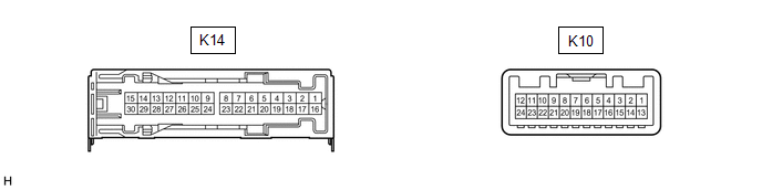
STEREO COMPONENT AMPLIFIER ASSEMBLY (for 9 Speakers)
|
Terminal No. (Symbol) | Wiring Color |
Terminal Description | Condition |
Specified Condition |
|---|---|---|---|---|
|
K14-1 (+B) - K14-3 (GND) |
L - W-B | Power source (+B) |
Always | 11 to 14 V |
|
K14-3 (GND) - Body ground |
W-B - Body ground | Ground |
Always | Below 1 V |
|
K14-8 (WF2+) - K14-3 (GND) |
W - W-B | Sound signal (Woofer) |
Audio system playing |
A waveform synchronized with sound signals is output |
|
K14-9 (RL+) - K14-3 (GND) |
B - W-B | Sound signal (Rear Left) |
Audio system playing |
A waveform synchronized with sound signals is output |
|
K14-10 (WF1+) - K14-3 (GND) |
BE - W-B | Sound signal (Woofer) |
Audio system playing |
A waveform synchronized with sound signals is output |
|
K14-11 (RR+) - K14-3 (GND) |
R - W-B | Sound signal (Rear Right) |
Audio system playing |
A waveform synchronized with sound signals is output |
|
K14-12 (TWL+) - K14-3 (GND) |
B - W-B | Sound signal (Front Left) |
Audio system playing |
A waveform synchronized with sound signals is output |
|
K14-13 (FL+) - K14-3 (GND) |
LG - W-B | Sound signal (Front Left) |
Audio system playing |
A waveform synchronized with sound signals is output |
|
K14-14 (TWR+) - K14-3 (GND) |
W - W-B*1 BE - W-B*2 |
Sound signal (Front Right) |
Audio system playing |
A waveform synchronized with sound signals is output |
|
K14-15 (FR+) - K14-3 (GND) |
BE - W-B | Sound signal (Front Right) |
Audio system playing |
A waveform synchronized with sound signals is output |
|
K14-16 (+B2) - K14-3 (GND) |
B - W-B | Power source (+B) |
Always | 11 to 14 V |
|
K14-18 (GND2) - Body ground |
W-B - Body ground | Ground |
Always | Below 1 V |
|
K14-23 (WF2-) - K14-3 (GND) |
R - W-B | Sound signal (Woofer) |
Audio system playing |
A waveform synchronized with sound signals is output |
|
K14-24 (RL-) - K14-3 (GND) |
LG - W-B | Sound signal (Rear Left) |
Audio system playing |
A waveform synchronized with sound signals is output |
|
K14-25 (WF1-) - K14-3 (GND) |
L - W-B | Sound signal (Woofer) |
Audio system playing |
A waveform synchronized with sound signals is output |
|
K14-26 (RR-) - K14-3 (GND) |
W - W-B | Sound signal (Rear Right) |
Audio system playing |
A waveform synchronized with sound signals is output |
|
K14-27 (TWL-) - K14-3 (GND) |
GR - W-B | Sound signal (Front Left) |
Audio system playing |
A waveform synchronized with sound signals is output |
|
K14-28 (FL-) - K14-3 (GND) |
W - W-B | Sound signal (Front Left) |
Audio system playing |
A waveform synchronized with sound signals is output |
|
K14-29 (TWR-) - K14-3 (GND) |
B - W-B*1 L - W-B*2 |
Sound signal (Front Right) |
Audio system playing |
A waveform synchronized with sound signals is output |
|
K14-30 (FR-) - K14-3 (GND) |
L - W-B | Sound signal (Front Right) |
Audio system playing |
A waveform synchronized with sound signals is output |
|
K10-1 (MUTE) - K14-3 (GND) |
BE - W-B |
Mute signal | Ignition switch ACC Audio system playing |
2.0 V or higher |
|
Audio system changing modes |
Below 1 V | |||
|
K10-2 (L-) - K14-3 (GND) |
G - W-B | Sound signal (Left) |
Audio system playing |
A waveform synchronized with sound signals is output |
|
K10-3 (L+) - K14-3 (GND) |
B - W-B | Sound signal (Left) |
Audio system playing |
A waveform synchronized with sound signals is output |
|
K10-4 (R-) - K14-3 (GND) |
R - W-B | Sound signal (Right) |
Audio system playing |
A waveform synchronized with sound signals is output |
|
K10-5 (R+) - K14-3 (GND) |
W - W-B | Sound signal (Right) |
Audio system playing |
A waveform synchronized with sound signals is output |
|
K10-6 (SLD) - Body ground |
Shield - Body ground |
Shield ground | Always |
Below 1 V |
|
K10-7 (TX-) | W |
AVC-LAN communication signal |
- | - |
|
K10-8 (TX+) | B |
AVC-LAN communication signal |
- | - |
|
K10-11 (SPD) - K14-3 (GND) |
G - W-B | Vehicle speed signal |
Ignition switch ON Wheel being rotated |
Pulse generation |
|
K10-12 (ACC) - K14-3 (GND) |
P - W-B | Power source (ACC) |
Ignition switch off | Below 1 V |
|
Ignition switch ACC | 11 to 14 V | |||
|
K10-14 (II1-) - K14-3 (GND) |
BR - W-B | Voice signal |
Voice guidance sounding |
A waveform synchronized with voice signals is output |
|
K10-15 (II1+) - K14-3 (GND) |
Y - W-B | Voice signal |
Voice guidance sounding |
A waveform synchronized with voice signals is output |
|
K10-18 (SLD1) - Body ground |
Shield - Body ground |
Shield ground | Always |
Below 1 V |
|
K10-24 (TMUT) - Body ground*1 |
R - Body ground |
Mute signal | Ignition switch ACC Audio system playing |
2.0 V or higher |
|
Emergency call mode | Below 1 V |
- *1: w/ Manual (SOS) Switch
- *2: w/o Manual (SOS) Switch
DCM (TELEMATICS TRANSCEIVER) (w/ Manual (SOS) Switch)
Click here
.gif)
COMBINATION METER ASSEMBLY
Click here
HEADUP DISPLAY (METER MIRROR SUB-ASSEMBLY) (w/ Headup Display System)
Click here
SKID CONTROL ECU (BRAKE ACTUATOR ASSEMBLY) (w/ ELECTRIC PARKING BRAKE SYSTEM)
Click here
READ NEXT:
 Dtc Check / Clear
DTC CHECK / CLEAR CHECK DTC (CHECK USING TECHSTREAM)
(a) Connect the Techstream to the DLC3. (b) Turn the ignition switch to ON and wait for 90 seconds.
(c) Turn the Techstream on. (d) Enter the f
Freeze Frame Data
FREEZE FRAME DATA CHECK FREEZE FRAME DATA (a) Connect the Techstream to the DLC3.
(b) Turn the ignition switch to ON. (c) Turn the Techstream on.
(d) Enter the following menus: Body Electrical / N
Diagnostic Trouble Code Chart
DIAGNOSTIC TROUBLE CODE CHART Audio and Visual System
DTC No. Detection Item
Link B1324
Lost Communication with Meter
B1325 Lost Communication with HUD
SEE MORE:
Precaution
PRECAUTION PRECAUTION FOR DISCONNECTING CABLE FROM NEGATIVE BATTERY TERMINAL
NOTICE: When disconnecting the cable from the negative (-) battery terminal, initialize the following system(s) after the cable is reconnected:
System Name See Procedure
Lane Tracing Assist System
Reporting safety defects
for U.S. owners
If you believe that your vehicle has a defect which could cause a
crash or could cause injury or death, you should immediately inform
the National Highway Traffic Safety Administration (NHTSA) in addition
to notifying Toyota Motor Sales, U.S.A., Inc. (Toll-free: 1-800-
331-4331).
If NHTSA recei
