Toyota Camry (XV70): Parts Location
PARTS LOCATION
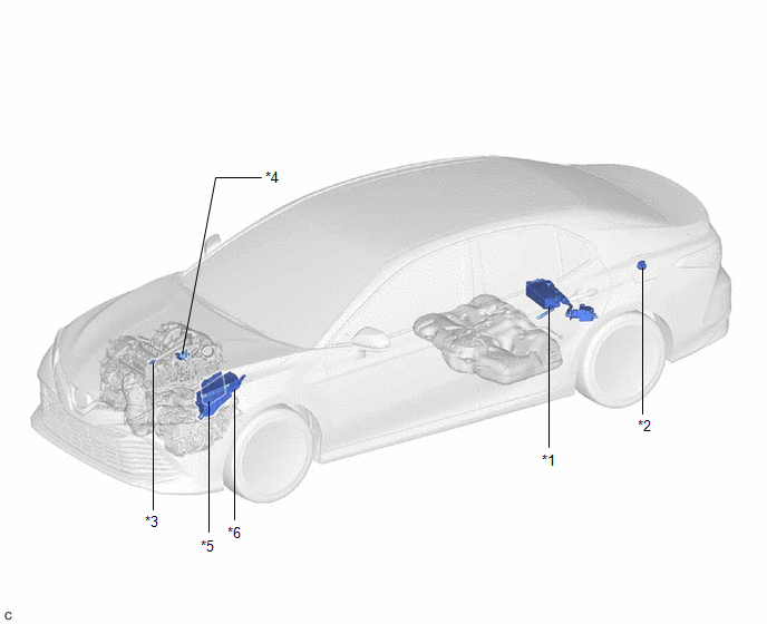
ILLUSTRATION
|
*1 | CANISTER (CHARCOAL CANISTER ASSEMBLY) |
*2 | FUEL TANK CAP ASSEMBLY |
|
*3 | PCV VALVE (VENTILATION VALVE SUB-ASSEMBLY) |
*4 | PURGE VALVE (PURGE VSV) |
|
*5 | ECM |
*6 | ENGINE ROOM RELAY BLOCK AND JUNCTION BLOCK ASSEMBLY - EFI-MAIN NO. 1 RELAY - EFI-MAIN NO. 1 FUSE |
READ NEXT:
 System Diagram
SYSTEM DIAGRAM
*1 Purge Valve (Purge VSV)
*2 Fuel Tank Cap Assembly
*3 Fuel Tank Assembly
*4 Canister Filter
*5 Fuel Cut-off Valve
*6 ECM
On-vehicle Inspection
ON-VEHICLE INSPECTION PROCEDURE
1. INSPECT FUEL CUT OPERATION (a) Start the engine. (b) Warm up the engine.
(c) Increase the engine speed to approximately 3500 rpm. (d) Use a sound scope to check
Fuel Tank Cap
InspectionINSPECTION PROCEDURE
1. INSPECT FUEL TANK CAP ASSEMBLY
(a) Visually check that the fuel tank cap assembly and gasket are not deformed or damaged.
If the result is not as specified
SEE MORE:
Ultrasonic Sensor (Front Left Center) Missing Message (C1AE287)
DESCRIPTION This DTC is stored when an open circuit or short occurs in the communication line between the front center ultrasonic sensor LH and the front center ultrasonic sensor RH, or when a malfunction occurs in the front center ultrasonic sensor LH.
DTC No. Detection Item
DTC Detect
Control Module Communication Bus "B" Off Bus Off (U007488,...,U015187)
DESCRIPTION The skid control ECU (brake actuator assembly) communicates with the following ECUs and sensors via CAN communication.
ECM
TCM (ECM)
Yaw rate and acceleration sensor (airbag sensor assembly)
Steering angle sensor
Power steering ECU (rack and pinion power steering gea
© 2023-2025 Copyright www.tocamry.com
